Namoo Buddha Films Pvt Ltd in association with Nawa Durga Club presents
Bishwa Jit Thapa Magar’s 1st production
Nepali movie – Lehsmo Osnang
Starring – Bishwa Jit Thapa Magar (as Lale), Khusbu Rana (as Khusbu), Shanti Ale (as Kali), Harimaya Thapa (Usha) etc.
Story/Direction/Production – Bishwa Jit Thapa Magar
Sunday, May 22, 2011
Sunday, May 8, 2011
Three Phase Motor
Generation and distribution

Animation of three-phase current flow


Large power generators provide an electric current at a potential which can be a few hundred volts or up to about 30 kV. At the power station, transformers step this voltage up to one suitable for transmission.
After numerous further conversions in the transmission and distribution network, the power is finally transformed to the standard utilization voltage for lighting and equipment. Single-phase loads are connected from one phase to neutral or between two phases. Three-phase loads such as larger motors must be connected to all three phases of the supply.
Three-wire versus four-wire
Three-phase circuits occur in two varieties. In one case, there are only three energized ("hot") wires; in the other case, there are three hot wires plus a neutral wire. Four-wire circuits offer flexibility, since a load may be connected "line-to-line" or "line-to-neutral"; three-wire circuits offer economy, since the neutral conductor is eliminated. Commonly, distribution voltage circuits are four-wire, while higher voltage transmission circuits are three-wire. Transmission lines often figure a ground wire, but this is solely for lightning protection and is not connected to deliver electrical power.Single-phase loads
Single-phase loads may be connected to a three-phase system in two ways. Either a load may be connected across two of the live conductors, or a load can be connected from a live phase conductor to the neutral conductor. Single-phase loads should be distributed evenly between the phases of the three-phase system for efficient use of the supply transformer and supply conductors. If the line-to-neutral voltage is a standard load voltage, for example 230 volt on a 400 volt three-phase system, single-phase loads can connect to a phase and the neutral. Loads can be distributed over three phases to balance the load. Where the line-to-neutral voltage is not the standard voltage for example 347 volts produced by a 600 V system, single-phase loads are connected through a step-down transformer.In a symmetrical three-phase system, the system neutral has the same magnitude of voltage to each of the three-phase conductors. The voltage between line conductors (Vl) is √3 times the phase conductor to neutral voltage (Vp). That is: Vl = √3Vp.
In some multiple-unit residential buildings of North America, three-phase power is supplied to the building but individual units have only single-phase power formed from two of the three supply phases. Lighting and convenience receptacles are connected from either phase conductor to neutral, giving the usual 120 V required by typical North American appliances. In the split-phase system, high-power loads are connected between the opposite "hot" poles, giving a voltage of 240 V. In some cases, they may be connected between phases of a three-phase system, giving a voltage of 208 V. This practice is common enough that 208 V single-phase equipment is readily available in North America. Attempts to use the more common 120/240 V equipment intended for split-phase distribution may result in poor performance since 240 V heating and lighting equipment will only produce 75% of its rating when operated at 208 V. Motors rated at 240 V will draw higher current at 208 V; some motors are dual-labelled for both voltages.
Where three-phase at low voltage is otherwise in use, it may still be split out into single-phase service cables through joints in the supply network or it may be delivered to a master distribution board (breaker panel) at the customer's premises. Connecting an electrical circuit from one phase to the neutral generally supplies the country's standard single phase voltage (120 V AC or 230 V AC) to the circuit.
The currents returning from the customers' premises to the supply transformer all share the neutral wire. If the loads are evenly distributed on all three phases, the sum of the returning currents in the neutral wire is approximately zero. Any unbalanced phase loading on the secondary side of the transformer will use the transformer capacity inefficiently.
If the supply neutral of a three-phase system with line-to-neutral connected loads is broken, the voltage balance on the loads will no longer be maintained. The neutral point will tend to drift toward the most heavily loaded phase, causing undervoltage conditions on that phase only. Correspondingly, the lightly loaded phases may approach the line-to-line voltage, which exceeds the line-to-neutral voltage by a factor of √3, causing overheating and failure of many types of loads.
For example, if several houses are connected through a 240 V transformer, which is connected to one phase of the three-phase system, each house might be affected by the imbalance on the three phase system. If the neutral connection is broken somewhere in the system, all equipment in a house might be damaged due to over-voltage. A similar phenomenon can exist if the house neutral (connected to the center tap of the 240 V pole transformer) is disconnected. This type of failure event can be difficult to troubleshoot if the drifting neutral effect is not understood. With inductive and/or capacitive loads, all phases can suffer damage as the reactive current moves across abnormal paths in the unbalanced system, especially if resonance conditions occur. For this reason, neutral connections are a critical part of a power distribution network and must be made as reliable as any of the phase connections.
Where a mixture of single-phase 120-volt lighting and three-phase, 240-volt motors are to be supplied, a system called high-leg delta is used.
Three-phase loads
Resistance heating loads such as electric boilers or space heating may be connected to three-phase systems. Electric lighting may also be similarly connected. These types of loads do not require the revolving magnetic field characteristic of three-phase motors but take advantage of the higher voltage and power level usually associated with three-phase distribution. Legacy fluorescent lighting systems also benefit from reduced flicker if adjacent fixtures are powered from different phases.
Large rectifier systems may have three-phase inputs; the resulting DC is easier to filter (smooth) than the output of a single-phase rectifier. Such rectifiers may be used for battery charging, electrolysis processes such as aluminium production or for operation of DC motors.
An interesting example of a three-phase load is the electric arc furnace used in steelmaking and in refining of ores.
In much of Europe, stoves are designed for a three-phase feed. Usually the individual heating units are connected between phase and neutral to allow for connection to a single-phase supply. In many areas of Europe, single-phase power is the only source available.
Phase converters
Occasionally the advantages of three-phase motors make it worthwhile to convert single-phase power to three-phase. Small customers, such as residential or farm properties, may not have access to a three-phase supply or may not want to pay for the extra cost of a three-phase service but may still wish to use three-phase equipment. Such converters may also allow the frequency to be varied allowing speed control. Some railway locomotives are moving to multi-phase motors driven by such systems even though the incoming supply to a locomotive is nearly always either DC or single-phase AC.Because single-phase power goes to zero at each moment that the voltage crosses zero but three-phase delivers power continuously, any such converter must have a way to store energy for the necessary fraction of a second.
One method for using three-phase equipment on a single-phase supply is with a rotary phase converter, essentially a three-phase motor with special starting arrangements and power factor correction that produces balanced three-phase voltages. When properly designed, these rotary converters can allow satisfactory operation of three-phase equipment such as machine tools on a single-phase supply. In such a device, the energy storage is performed by the mechanical inertia (flywheel effect) of the rotating components. An external flywheel is sometimes found on one or both ends of the shaft.
A second method that was popular in the 1940s and 1950s was the transformer method. At that time, capacitors were more expensive than transformers, so an autotransformer was used to apply more power through fewer capacitors. This method performs well and does have supporters, even today. The usage of the name transformer method separated it from another common method, the static converter, as both methods have no moving parts, which separates them from the rotary converters.
Another method often attempted is with a device referred to as a static phase converter. This method of running three-phase equipment is commonly attempted with motor loads though it only supplies ⅔ power and can cause the motor loads to run hot and in some cases overheat. This method does not work when sensitive circuitry is involved such as CNC devices or in induction and rectifier-type loads.
Some devices are made which create an imitation three-phase from three-wire single-phase supplies. This is done by creating a third "subphase" between the two live conductors, resulting in a phase separation of 180° − 90° = 90°. Many three-phase devices can run on this configuration but at lower efficiency.
Variable-frequency drives (also known as solid-state inverters) are used to provide precise speed and torque control of three-phase motors. Some models can be powered by a single-phase supply. VFDs work by converting the supply voltage to DC and then converting the DC to a suitable three-phase source for the motor.
Digital phase converters are designed for fixed-frequency operation from a single-phase source. Similar to a variable-frequency drive, they use a microprocessor to control solid-state power switching components to maintain balanced three-phase voltages.
Alternatives to three-phase
- Split-phase electric power is used when three-phase power is not available and allows double the normal utilization voltage to be supplied for high-power loads.
- Two-phase electric power, like three-phase, gives constant power transfer to a linear load. For loads that connect each phase to neutral, assuming the load is the same power draw, the two-wire system has a neutral current which is greater than neutral current in a three-phase system. Also motors are not entirely linear, which means that despite the theory, motors running on three-phase tend to run smoother than those on two-phase. The generators in the Adams Power Plant at Niagara Falls which were installed in 1895 were the largest generators in the world at the time and were two-phase machines. True two-phase power distribution is essentially obsolete. Special-purpose systems may use a two-phase system for control. Two-phase power may be obtained from a three-phase system using an arrangement of transformers called a Scott-T transformer.
- Monocyclic power was a name for an asymmetrical modified two-phase power system used by General Electric around 1897, championed by Charles Proteus Steinmetz and Elihu Thomson. This system was devised to avoid patent infringement. In this system, a generator was wound with a full-voltage single-phase winding intended for lighting loads and with a small (usually ¼ of the line voltage) winding which produced a voltage in quadrature with the main windings. The intention was to use this "power wire" additional winding to provide starting torque for induction motors, with the main winding providing power for lighting loads. After the expiration of the Westinghouse patents on symmetrical two-phase and three-phase power distribution systems, the monocyclic system fell out of use; it was difficult to analyze and did not last long enough for satisfactory energy metering to be developed.
- High-phase-order systems for power transmission have been built and tested. Such transmission lines use six (two-pole, three-phase) or twelve (two-pole, six-phase) lines and employ design practices characteristic of extra-high-voltage transmission lines. High-phase-order transmission lines may allow transfer of more power through a given transmission line right-of-way without the expense of a high-voltage direct current (HVDC) converter at each end of the line.

- SPACE VECTORSSpace vector representation of the mmf distribution in an AC machine created by balanced positive-sequence three-phase sinusoidal currents. Each of the ABC (RGB) space vectors pulsates along its respective axis. The resultant vector (in black), of 1.5 magnitude, rotates at the excitation frequency.
AC Motors
AC motors are also fairly simple to understand. They are a little trickier to make but will need single-phase or three-phase AC power to make them work. In the little diagrams above, we have a squirrel cage ac induction motor, a permanent magnet synchronous machine, and a synchronous motor. The inventor of the three-phase AC motor was Nikola Tesla, a pioneer in electromagnetism.
Here are some great sites which describe how AC motors work and how to design them.
http://www.motorsoft.net/
http://www.magsoft-flux.com/ (shows a Flux2D animation of the fields within a motor)
http://www.ece.umn.edu/users/riaz/animations/spacevectors.html Great animations!
There are a couple types of basic AC motors you can build. They also make super science fair projects.
http://www.eskimo.com/~billb/maglev/linmot.txt
http://www.italtec.it/enkitmo.htm
A Very Simple AC Motor
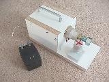
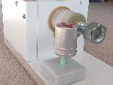
Here is a photo of a very simple eddy current AC motor I put together. I think this one wins the prize for the Simplest AC Motor you can make. It works great and is very easy to build. I found the original plans in a book titled: "Physics Demonstration Experiments" by Harry F. Meiners, Vol 2, Ronald Press Co., NY, 1970, LCCC #69-14674. With some experimentation, I found that the can spins faster when the nut is on the end of the bolt than when the nut is removed. What do you think will happen if the rotor is moved to the other side of the bolt? It consists of a coil mounted onto a 3/4" bolt. The coil is about 100' of 20AWG wire, on a form about 1.5" long, with a dc resistance of about 1.2 ohms, and an inductance of about 2.4mH as an air-core inductor. The voltage supplied to the coil is 19Vac from a plug-in transformer and supplies about 2.5Aac to the coil. The rotor is an aluminum film canister (today they use plastic, but you might still find a few of these around - ask your friends) with a dimple in the bottom of it, resting on a pencil. (I figured that the graphite in the pencil will lubricate the rotor.)
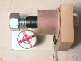
The eddy current motor on the left has two rotors, they spin in opposite directions. The set-up on the right shows a variac, multimeter, eddy current motor, and a calibrated strobe. With this, we could plot speed vs. voltage. We found that the rotor would spin about 1000 rpm with 120V applied to it. Can't keep it there for long, since the coil and bolt get real hot. On these two coils, a smaller diameter wire was used, so the dc resistance was about 11.2 ohms, and 24mH as an air-core inductor. With this, we could apply 120Vac to it and only 2 amps would be drawn.
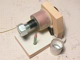
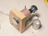
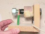
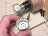

This shows the basic construction. The bolt is a 4" long 3/4-13 bolt, the wood is 3/4" thick. I put a small dimple into the bottom of the aluminum film canister so it would sit onto the pencil point. The red strips of tape helped with the strobe and looks cool as it spins. I found that the nut on the end of the bolt makes it go faster.
A Shaded Pole AC Motor
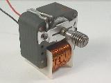
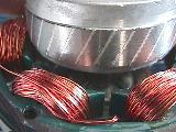
Here is a photo of a typical shaded pole motor. See the close-up of the notch in the laminations and the extra heavy winding of two turns creating the phase difference between the two sections of the laminations, giving the magnetic field a directional motion. The rotor spins CW as seen from the end with the screw on the shaft. Motors like this are used in thousands of applications.
Another Shaded Pole AC Motor
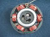
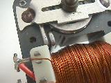
Here is a photo of a ceiling fan motor, also shaded pole, but with six windings instead of only one as seen above. The rotor laminations are skewed to provide smoother torque. The pole pieces with the windings have a slot in them to create a delayed flux, creating a direction for rotation.
A Universal Motor
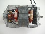
And here is a photo of a universal motor. It has brushes like a DC motor, but will operate on AC or DC.
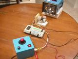
A 3-Phase AC Motor Demonstrator
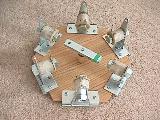
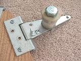

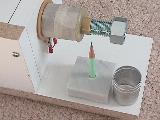
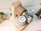
Here is a project my daughter is working on. It shows how a 3-phase AC motor works with a rotating magnetic field and a permanent magnet rotor, making it a synchronous AC motor. We have pushbuttons which allow the user to turn on any one of the pairs of opposite coils, in either a N-S or a S-N orientation. For example, the green button turns on the horizontal pair of coils in a S-N orientation. The yellow button turns on the horizontal pair of coils in a N-S orientation. On each coil is a bi-color LED to indicate the magnetic polarity of the coil when it is turned on. The power to the coils (each pair connected in parallel) is supplied by a 5v computer power supply. The coils draw about 4amps at 5Vdc each, so a supply with 23amps available is a great match. Each coil is mounted on a 3/4" bolt, attached to a hinge. This way, sets of coils can be folded down out of the way to show how a shaded pole motor works. The rotor is a bar of steel with a NIB magnet on each end. The rotor does oscillate a bit when going from coil to coil.
Here's more photos:
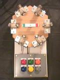
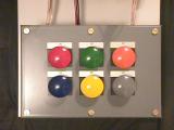
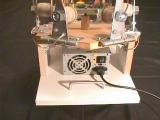


By pressing the colored buttons in the correct sequence, the rotor will follow the magnetic field in a clockwise fashion. The faster you go through the sequence, the faster the rotor will rotate. This shows that the speed of this motor is dependant on the frequency of the power applied to it. The higher the frequency, the faster it goes. At 60Hz, it would rotate at 1 revolution/cycle * 60 cycles/sec * 60 sec/min = 3600 revolutions per minute or rpm.
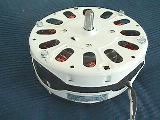
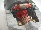
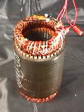
Three Phase AC Motor Stator
Industrial AC Motors
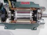
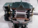
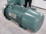
These are cut-aways of actual industrial three phase AC motors. They have different HP ratings, from 5hp, 2hp, 900hp. They are manufactured by Reliance Electric (used to be part of Rockwell Automation, now part of Baldor Electric).
Linear motors
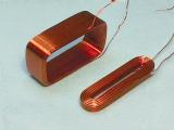
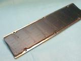
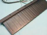
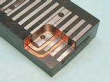
A linear motor is like an ac motor, but it is unwrapped and laid out flat. The photos show parts of linear motors. Some have flat coils and magnet sections, others are "T" shaped. Check www.anorad.com for more info.
More information is available in these two excellent articles:
http://www-cdr.stanford.edu/dynamic/linear_engine/eng_ref/electric_motors/motion1.pdf
http://www-cdr.stanford.edu/dynamic/linear_engine/eng_ref/electric_motors/motion2.pdf
More on direct drive linear motors:
http://www.ifr.mavt.ethz.ch/publications/sprenger97a.pdf
http://www.ifr.mavt.ethz.ch/publications/sprenger98.pdf
Saturday, May 7, 2011
Alternator
History
Alternating current generating systems were known in simple forms from the discovery of the magnetic induction of electric current. The early machines were developed by pioneers such as Michael Faraday and Hippolyte Pixii.
Faraday developed the "rotating rectangle", whose operation was heteropolar - each active conductor passed successively through regions where the magnetic field was in opposite directions.[1] The first public demonstration of a more robust "alternator system" took place in 1886.[2] Large two-phase alternating current generators were built by a British electrician, J.E.H. Gordon, in 1882. Lord Kelvin and Sebastian Ferranti also developed early alternators, producing frequencies between 100 and 300 Hz. In 1891, Nikola Tesla patented a practical "high-frequency" alternator (which operated around 15 kHz).[3] After 1891, polyphase alternators were introduced to supply currents of multiple differing phases.[4] Later alternators were designed for varying alternating-current frequencies between sixteen and about one hundred hertz, for use with arc lighting, incandescent lighting and electric motors.[5]
Principle of operation

Diagram of a simple alternator with a rotating magnetic core (rotor) and stationary wire (stator) also showing the current induced in the stator by the rotating magnetic field of the rotor.
Alternators generate electricity using the same principle as DC generators, namely, when the magnetic field around a conductor changes, a current is induced in the conductor. Typically, a rotating magnet, called the rotor turns within a stationary set of conductors wound in coils on an iron core, called the stator. The field cuts across the conductors, generating an induced EMF(Electro-Magnetic Field), as the mechanical input causes the rotor to turn.
The rotating magnetic field induces an AC voltage in the stator windings. Often there are three sets of stator windings, physically offset so that the rotating magnetic field produces a three phase current, displaced by one-third of a period with respect to each other.
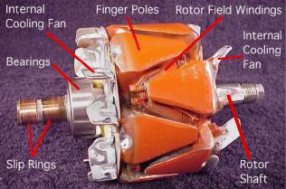
The rotors magnetic field may be produced by induction (as in a "brush-less" alternator), by permanent magnets (as in very small machines), or by a rotor winding energized with direct current through slip rings and brushes. The rotors magnetic field may even be provided by stationary field winding, with moving poles in the rotor. Automotive alternators invariably use a rotor winding, which allows control of the alternators generated voltage by varying the current in the rotor field winding. Permanent magnet machines avoid the loss due to magnetizing current in the rotor, but are restricted in size, owing to the cost of the magnet material. Since the permanent magnet field is constant, the terminal voltage varies directly with the speed of the generator. Brushless AC generators are usually larger machines than those used in automotive applications.
An automatic voltage control device controls the field current to keep output voltage constant. If the output voltage from the stationary armature coils drops due to an increase in demand, more current is fed into the rotating field coils through the Automatic Voltage Regulator or AVR. This increases the magnetic field around the field coils which induces a greater voltage in the armature coils. Thus, the output voltage is brought back up to its original value.
Alternators in central power stations use may also control the field current to regulate reactive power and to help stabilize the power system against the effects of momentary faults.
Synchronous speeds
The output frequency of an alternator depends on the number of poles and the rotational speed. The speed corresponding to a particular frequency is called the synchronous speed for that frequency. This table[6] gives some examples:
| Poles | RPM at 50 Hz | RPM at 60 Hz |
|---|---|---|
| 2 | 3,000 | 3,600 |
| 4 | 1,500 | 1,800 |
| 6 | 1,000 | 1,200 |
| 8 | 750 | 900 |
| 10 | 600 | 720 |
| 12 | 500 | 600 |
| 14 | 428.6 | 514.3 |
| 16 | 375 | 450 |
| 18 | 333.3 | 400 |
| 20 | 300 | 360 |
More generally, one cycle of alternating current is produced each time a pair of field poles passes over a point on the stationary winding. The relation between speed and frequency is N = 120f / P , where f is the frequency in Hz (cycles per second). P is the number of poles (2,4,6...) and N is the rotational speed in revolutions per minute (RPM). Very old descriptions of alternating current systems sometimes give the frequency in terms of alternations per minute, counting each half-cycle as one alternation; so 12,000 alternations per minute corresponds to 100 Hz.
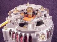
Automotive alternators


Cut-away of an alternator, showing the claw-pole construction; two of the wedge-shaped field poles, alternating N and S, are visible in the centre and the stationary armature winding is visible at the top and bottom of the opening. The belt and pulley at the right hand end drives the alternator.
Alternators are used in modern automobiles to charge the battery and to power a car's electric system when its engine is running. Alternators have the great advantage over direct-current generators of not using a commutator, which makes them simpler, lighter, less costly, and more rugged than a DC generator, and the slip rings allow for greatly extended brush life. The stronger construction of automotive alternators allows them to use a smaller pulley so as to turn faster than the engine, improving output when the engine is idling. The availability of low-cost solid-state diodes from 1960 onward allowed car manufacturers to substitute alternators for DC generators (major American manufacturers had made the transition to alternators by 1962, for example). Automotive alternators use a set of rectifiers (diode bridge) to convert AC to DC. To provide direct current with low ripple, automotive alternators have a three-phase winding. In addition, the pole-pieces of the rotor are shaped (claw-pole) so as to produce a voltage waveform closer to a square wave that, when rectified by the diodes, produces even less ripple than the rectification of three-phase sinusoidal voltages.
Typical passenger vehicle and light truck alternators use Lundell or claw-pole field construction, where the field north and south poles are all energized by a single winding, with the poles looking rather like fingers of two hands interlocked with each other. Larger vehicles may have salient-pole alternators similar to larger machines. The automotive alternator is usually belt driven at 2-3 times the engine crankshaft speed. Automotive alternators are not restricted to a certain RPM because the alternating current is rectified to direct current and need not be any constant frequency.
Modern automotive alternators have a voltage regulator built into them. The voltage regulator operates by modulating the small field current in order to produce a constant voltage at the stator output. The field current is much smaller than the output current of the alternator; for example, a 70 A alternator may need only 2 A of field current. The field current is supplied to the rotor windings by slip rings and brushes. The low current and relatively smooth slip rings ensure greater reliability and longer life than that obtained by a DC generator with its commutator and higher current being passed through its brushes.
Efficiency of automotive alternators is limited by fan cooling loss, bearing loss, iron loss, copper loss, and the voltage drop in the diode bridges; at part load, efficiency is between 50-62% depending on the size of alternator, and varies with alternator speed.[7] In comparison, very small high-performance permanent magnet alternators, such as those used for bicycle lighting systems, achieve an efficiency around 60%. Larger permanent magnet alternators can achieve much higher efficiency.[citation needed] By contrast, the large AC generators used in power stations run at carefully controlled speeds and have no constraints on size or weight. Consequently, they have much higher efficiencies, on the order of 98% from shaft to AC output power.
The field windings are initially supplied via the ignition switch and charge warning light, which is why the light is on when the ignition is on but the engine is not running. Once the engine is running and the alternator is generating, a diode feeds the field current from the alternator main output, thus equalizing the voltage across the warning light which goes off. The wire supplying the field current is often referred to as the "exciter" wire. The drawback of this arrangement is that if the warning light fails or the "exciter" wire is disconnected, no excitation current reaches the alternator field windings and so the alternator, due to low residual magnetism in the rotor, will not generate any power. However, some alternators will self-excite when the engine is revved to a certain speed. Also, some warning light circuits are equipped with a resistor in parallel with the warning light that will permit excitation current to flow even if the warning light fails. The driver should check that the warning light is on when the engine is stopped; otherwise, there might not be any indication of a failure of the alternator drive belt which normally also drives the cooling water pump.
Very large automotive alternators used on buses, heavy equipment or emergency vehicles may produce 300 amperes. Very old automobiles with minimal lighting and electronic devices may have only a 30 A alternator. Typical passenger car and light truck alternators are rated around 50-70 A, though higher ratings are becoming more common, especially as there is more load on the vehicle's electrical system with, for example, the introduction of air conditioning and electric power steering systems. Semi-trucks usually have alternators around 140 amperes. Very large automotive alternators may be water-cooled or oil-cooled.
Many alternator voltage regulators are today linked to the vehicle's onboard computer system and, in recent years, other factors including air temperature (obtained from the intake air temperature sensor or battery temperature sensor in many cases) and engine load are considered in adjusting the battery charging voltage supplied by the alternator.
Marine alternators
Marine alternators used in yachts are similar to automotive alternators, with appropriate adaptations to the salt-water environment. Marine alternators are designed to be explosion proof so that brush sparking will not ignite explosive gas mixtures in an engine room environment. They may be 12 or 24 volt depending on the type of system installed. Larger marine diesels may have two or more alternators to cope with the heavy electrical demand of a modern yacht. On single alternator circuits, the power is split between the engine starting battery and the domestic or house battery (or batteries) by use of a split-charge diode (battery isolator) or a mechanical switch. Because the alternator only produces power when running, engine control panels are typically fed directly from the alternator by means of an auxiliary terminal. Other typical connections are for charge control circuits.
Brushless alternators
A brushless alternator is composed of two alternators built end-to-end on one shaft. Smaller brushless alternators may look like one unit but the two parts are readily identifiable on the large versions. The larger of the two sections is the main alternator and the smaller one is the exciter. The exciter has stationary field coils and a rotating armature (power coils). The main alternator uses the opposite configuration with a rotating field and stationary armature. A bridge rectifier, called the rotating rectifier assembly, is mounted on a plate attached to the rotor. Neither brushes nor slip rings are used, which reduces the number of wearing parts. The main alternator has a rotating field as described above and a stationary armature (power generation windings).
Varying the amount of current through the stationary exciter field coils varies the 3-phase output from the exciter. This output is rectified by a rotating rectifier assembly, mounted on the rotor, and the resultant DC supplies the rotating field of the main alternator and hence alternator output. The result of all this is that a small DC exciter current indirectly controls the output of the main alternator.
Hybrid automobiles
Hybrid automobiles replace the separate alternator and starter motor with a combined motor/generator that performs both functions, cranking the internal combustion engine when starting, providing additional mechanical power for accelerating, and charging a large storage battery when the vehicle is running at constant speed. These rotating machines have considerably more powerful electronic devices for their control than the automotive alternator described above.
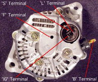
| Understanding the Alternator |
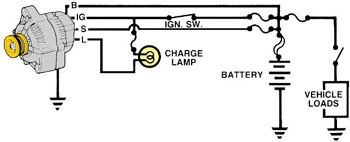 | ||||
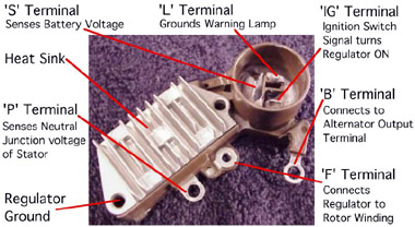
| Four wires connect the alternator to the rest of the charging system. 'B' is the alternator output wire that supplies current to the battery. 'IG' is the ignition input that turns on the alternator/regulator assembly. 'S' is used by the regulator to monitor charging voltage at the battery. 'L' is the wire the regulator uses to ground the charge warning lamp.
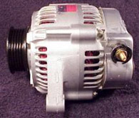
The Alternator Assembly 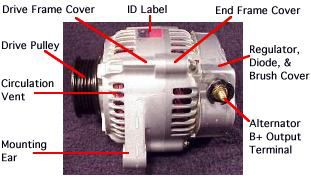 |
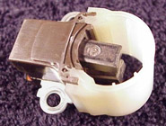
 | The alternator contains: A rotating field winding called the rotor. A stationary induction winding called the stator. A diode assembly called the rectifier bridge. A control device called the voltage regulator. Two internal fans to promote air circulation. |
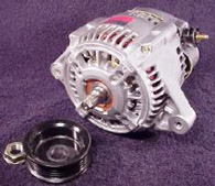 | Alternator drive pulleys either bolt on or are pressed on the rotor shaft. Both 'V' and Multi-grove types are used. Note this alternator does not have an external fan as part of the pulley assembly. While many manufacturers do use a external fan for cooling. This alternator has two internal fans to draw air in for cooling. |
|
|
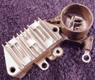 | The regulator is the brain of the charging system. It monitors both battery and stator voltages and depending on the measured voltages, the regulator will adjust the amount of rotor field current to control alternator output. Regulators can be mounted both internal or external. Current technology uses an internal regulator. |
 |
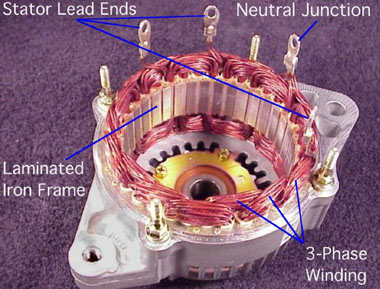
 Stator Designs Stator Designs |  |
| Wye wound stators have three windings with a common neutral junction. They can be identified because they have 4 stator lead ends. Wye wound stators are used in alternators that require high voltage output at low alternator speeds. Two windings are in series at any one time during charge output. |
 |
| Delta wound stators can be identified because they have only three stator lead ends. Delta stators allow for higher current flow being delivered at low RPM. The windings are in parallel rather than series as like the Wye design. |
 |
 | Two diodes are connected to each stator lead. One positive the other negative. Because a single diode will only block half the the AC voltage. Six or eight diodes are used to rectify the AC stator voltage to DC voltage. Diodes used in this configuration will redirect both the positive and negative polarity signals of the AC voltage to produce DC voltage. This process is called 'Full - Wave Rectification'. |
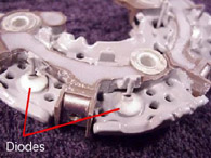 | Diodes are used as one-way electrical check valves. Passing current in only one direction, never in reverse. Diodes are mounted in a heat sink to dissipate the heat generated by the diodes. Diodes redirect the AC voltage into DC voltage so the battery receives the correct polarity. |
Rectifier Operation  |
| In red you can see B+ current pass through to the rectifier as it goes to the battery. In green you can see the return path. Electronic Regulator |
Subscribe to:
Posts (Atom)
ani ...........
