History
Alternating current generating systems were known in simple forms from the discovery of the magnetic induction of electric current. The early machines were developed by pioneers such as Michael Faraday and Hippolyte Pixii.
Faraday developed the "rotating rectangle", whose operation was heteropolar - each active conductor passed successively through regions where the magnetic field was in opposite directions.[1] The first public demonstration of a more robust "alternator system" took place in 1886.[2] Large two-phase alternating current generators were built by a British electrician, J.E.H. Gordon, in 1882. Lord Kelvin and Sebastian Ferranti also developed early alternators, producing frequencies between 100 and 300 Hz. In 1891, Nikola Tesla patented a practical "high-frequency" alternator (which operated around 15 kHz).[3] After 1891, polyphase alternators were introduced to supply currents of multiple differing phases.[4] Later alternators were designed for varying alternating-current frequencies between sixteen and about one hundred hertz, for use with arc lighting, incandescent lighting and electric motors.[5]
Principle of operation

Diagram of a simple alternator with a rotating magnetic core (rotor) and stationary wire (stator) also showing the current induced in the stator by the rotating magnetic field of the rotor.
Alternators generate electricity using the same principle as DC generators, namely, when the magnetic field around a conductor changes, a current is induced in the conductor. Typically, a rotating magnet, called the rotor turns within a stationary set of conductors wound in coils on an iron core, called the stator. The field cuts across the conductors, generating an induced EMF(Electro-Magnetic Field), as the mechanical input causes the rotor to turn.
The rotating magnetic field induces an AC voltage in the stator windings. Often there are three sets of stator windings, physically offset so that the rotating magnetic field produces a three phase current, displaced by one-third of a period with respect to each other.
The rotors magnetic field may be produced by induction (as in a "brush-less" alternator), by permanent magnets (as in very small machines), or by a rotor winding energized with direct current through slip rings and brushes. The rotors magnetic field may even be provided by stationary field winding, with moving poles in the rotor. Automotive alternators invariably use a rotor winding, which allows control of the alternators generated voltage by varying the current in the rotor field winding. Permanent magnet machines avoid the loss due to magnetizing current in the rotor, but are restricted in size, owing to the cost of the magnet material. Since the permanent magnet field is constant, the terminal voltage varies directly with the speed of the generator. Brushless AC generators are usually larger machines than those used in automotive applications.
An automatic voltage control device controls the field current to keep output voltage constant. If the output voltage from the stationary armature coils drops due to an increase in demand, more current is fed into the rotating field coils through the Automatic Voltage Regulator or AVR. This increases the magnetic field around the field coils which induces a greater voltage in the armature coils. Thus, the output voltage is brought back up to its original value.
Alternators in central power stations use may also control the field current to regulate reactive power and to help stabilize the power system against the effects of momentary faults.
Synchronous speeds
The output frequency of an alternator depends on the number of poles and the rotational speed. The speed corresponding to a particular frequency is called the synchronous speed for that frequency. This table[6] gives some examples:
| Poles | RPM at 50 Hz | RPM at 60 Hz |
|---|---|---|
| 2 | 3,000 | 3,600 |
| 4 | 1,500 | 1,800 |
| 6 | 1,000 | 1,200 |
| 8 | 750 | 900 |
| 10 | 600 | 720 |
| 12 | 500 | 600 |
| 14 | 428.6 | 514.3 |
| 16 | 375 | 450 |
| 18 | 333.3 | 400 |
| 20 | 300 | 360 |
More generally, one cycle of alternating current is produced each time a pair of field poles passes over a point on the stationary winding. The relation between speed and frequency is N = 120f / P , where f is the frequency in Hz (cycles per second). P is the number of poles (2,4,6...) and N is the rotational speed in revolutions per minute (RPM). Very old descriptions of alternating current systems sometimes give the frequency in terms of alternations per minute, counting each half-cycle as one alternation; so 12,000 alternations per minute corresponds to 100 Hz.
Automotive alternators


Cut-away of an alternator, showing the claw-pole construction; two of the wedge-shaped field poles, alternating N and S, are visible in the centre and the stationary armature winding is visible at the top and bottom of the opening. The belt and pulley at the right hand end drives the alternator.
Alternators are used in modern automobiles to charge the battery and to power a car's electric system when its engine is running. Alternators have the great advantage over direct-current generators of not using a commutator, which makes them simpler, lighter, less costly, and more rugged than a DC generator, and the slip rings allow for greatly extended brush life. The stronger construction of automotive alternators allows them to use a smaller pulley so as to turn faster than the engine, improving output when the engine is idling. The availability of low-cost solid-state diodes from 1960 onward allowed car manufacturers to substitute alternators for DC generators (major American manufacturers had made the transition to alternators by 1962, for example). Automotive alternators use a set of rectifiers (diode bridge) to convert AC to DC. To provide direct current with low ripple, automotive alternators have a three-phase winding. In addition, the pole-pieces of the rotor are shaped (claw-pole) so as to produce a voltage waveform closer to a square wave that, when rectified by the diodes, produces even less ripple than the rectification of three-phase sinusoidal voltages.
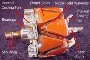
Typical passenger vehicle and light truck alternators use Lundell or claw-pole field construction, where the field north and south poles are all energized by a single winding, with the poles looking rather like fingers of two hands interlocked with each other. Larger vehicles may have salient-pole alternators similar to larger machines. The automotive alternator is usually belt driven at 2-3 times the engine crankshaft speed. Automotive alternators are not restricted to a certain RPM because the alternating current is rectified to direct current and need not be any constant frequency.
Modern automotive alternators have a voltage regulator built into them. The voltage regulator operates by modulating the small field current in order to produce a constant voltage at the stator output. The field current is much smaller than the output current of the alternator; for example, a 70 A alternator may need only 2 A of field current. The field current is supplied to the rotor windings by slip rings and brushes. The low current and relatively smooth slip rings ensure greater reliability and longer life than that obtained by a DC generator with its commutator and higher current being passed through its brushes.
Efficiency of automotive alternators is limited by fan cooling loss, bearing loss, iron loss, copper loss, and the voltage drop in the diode bridges; at part load, efficiency is between 50-62% depending on the size of alternator, and varies with alternator speed.[7] In comparison, very small high-performance permanent magnet alternators, such as those used for bicycle lighting systems, achieve an efficiency around 60%. Larger permanent magnet alternators can achieve much higher efficiency.[citation needed] By contrast, the large AC generators used in power stations run at carefully controlled speeds and have no constraints on size or weight. Consequently, they have much higher efficiencies, on the order of 98% from shaft to AC output power.
The field windings are initially supplied via the ignition switch and charge warning light, which is why the light is on when the ignition is on but the engine is not running. Once the engine is running and the alternator is generating, a diode feeds the field current from the alternator main output, thus equalizing the voltage across the warning light which goes off. The wire supplying the field current is often referred to as the "exciter" wire. The drawback of this arrangement is that if the warning light fails or the "exciter" wire is disconnected, no excitation current reaches the alternator field windings and so the alternator, due to low residual magnetism in the rotor, will not generate any power. However, some alternators will self-excite when the engine is revved to a certain speed. Also, some warning light circuits are equipped with a resistor in parallel with the warning light that will permit excitation current to flow even if the warning light fails. The driver should check that the warning light is on when the engine is stopped; otherwise, there might not be any indication of a failure of the alternator drive belt which normally also drives the cooling water pump.
Very large automotive alternators used on buses, heavy equipment or emergency vehicles may produce 300 amperes. Very old automobiles with minimal lighting and electronic devices may have only a 30 A alternator. Typical passenger car and light truck alternators are rated around 50-70 A, though higher ratings are becoming more common, especially as there is more load on the vehicle's electrical system with, for example, the introduction of air conditioning and electric power steering systems. Semi-trucks usually have alternators around 140 amperes. Very large automotive alternators may be water-cooled or oil-cooled.
Many alternator voltage regulators are today linked to the vehicle's onboard computer system and, in recent years, other factors including air temperature (obtained from the intake air temperature sensor or battery temperature sensor in many cases) and engine load are considered in adjusting the battery charging voltage supplied by the alternator.
Marine alternators
Marine alternators used in yachts are similar to automotive alternators, with appropriate adaptations to the salt-water environment. Marine alternators are designed to be explosion proof so that brush sparking will not ignite explosive gas mixtures in an engine room environment. They may be 12 or 24 volt depending on the type of system installed. Larger marine diesels may have two or more alternators to cope with the heavy electrical demand of a modern yacht. On single alternator circuits, the power is split between the engine starting battery and the domestic or house battery (or batteries) by use of a split-charge diode (battery isolator) or a mechanical switch. Because the alternator only produces power when running, engine control panels are typically fed directly from the alternator by means of an auxiliary terminal. Other typical connections are for charge control circuits.
Brushless alternators
A brushless alternator is composed of two alternators built end-to-end on one shaft. Smaller brushless alternators may look like one unit but the two parts are readily identifiable on the large versions. The larger of the two sections is the main alternator and the smaller one is the exciter. The exciter has stationary field coils and a rotating armature (power coils). The main alternator uses the opposite configuration with a rotating field and stationary armature. A bridge rectifier, called the rotating rectifier assembly, is mounted on a plate attached to the rotor. Neither brushes nor slip rings are used, which reduces the number of wearing parts. The main alternator has a rotating field as described above and a stationary armature (power generation windings).
Varying the amount of current through the stationary exciter field coils varies the 3-phase output from the exciter. This output is rectified by a rotating rectifier assembly, mounted on the rotor, and the resultant DC supplies the rotating field of the main alternator and hence alternator output. The result of all this is that a small DC exciter current indirectly controls the output of the main alternator.
Hybrid automobiles
Hybrid automobiles replace the separate alternator and starter motor with a combined motor/generator that performs both functions, cranking the internal combustion engine when starting, providing additional mechanical power for accelerating, and charging a large storage battery when the vehicle is running at constant speed. These rotating machines have considerably more powerful electronic devices for their control than the automotive alternator described above.
| Understanding the Alternator |
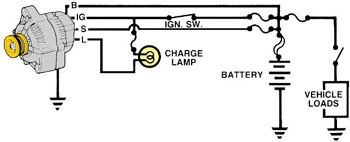 | ||||
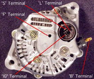
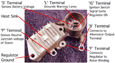
| Four wires connect the alternator to the rest of the charging system. 'B' is the alternator output wire that supplies current to the battery. 'IG' is the ignition input that turns on the alternator/regulator assembly. 'S' is used by the regulator to monitor charging voltage at the battery. 'L' is the wire the regulator uses to ground the charge warning lamp.
The Alternator Assembly 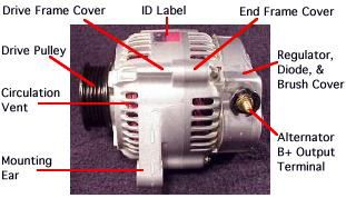 |
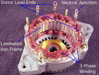
 | The alternator contains: A rotating field winding called the rotor. A stationary induction winding called the stator. A diode assembly called the rectifier bridge. A control device called the voltage regulator. Two internal fans to promote air circulation. |
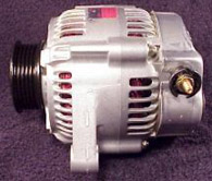
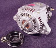 | Alternator drive pulleys either bolt on or are pressed on the rotor shaft. Both 'V' and Multi-grove types are used. Note this alternator does not have an external fan as part of the pulley assembly. While many manufacturers do use a external fan for cooling. This alternator has two internal fans to draw air in for cooling. |
|
|
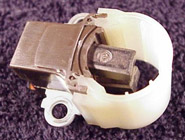
 | The regulator is the brain of the charging system. It monitors both battery and stator voltages and depending on the measured voltages, the regulator will adjust the amount of rotor field current to control alternator output. Regulators can be mounted both internal or external. Current technology uses an internal regulator. |
 |
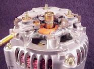
 Stator Designs Stator Designs |  |
| Wye wound stators have three windings with a common neutral junction. They can be identified because they have 4 stator lead ends. Wye wound stators are used in alternators that require high voltage output at low alternator speeds. Two windings are in series at any one time during charge output. |
 |
| Delta wound stators can be identified because they have only three stator lead ends. Delta stators allow for higher current flow being delivered at low RPM. The windings are in parallel rather than series as like the Wye design. |
 |
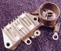
 | Two diodes are connected to each stator lead. One positive the other negative. Because a single diode will only block half the the AC voltage. Six or eight diodes are used to rectify the AC stator voltage to DC voltage. Diodes used in this configuration will redirect both the positive and negative polarity signals of the AC voltage to produce DC voltage. This process is called 'Full - Wave Rectification'. |
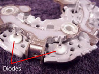 | Diodes are used as one-way electrical check valves. Passing current in only one direction, never in reverse. Diodes are mounted in a heat sink to dissipate the heat generated by the diodes. Diodes redirect the AC voltage into DC voltage so the battery receives the correct polarity. |
Rectifier Operation  |
| In red you can see B+ current pass through to the rectifier as it goes to the battery. In green you can see the return path. Electronic Regulator |

No comments:
Post a Comment