Transformer
This article is about the electrical device . For the toy line franchise, see Transformers. For other uses, see Transformer (disambiguation).

Pole-mounted power distribution transformer with center-tapped secondary winding (note use of grounded conductor, right, as one leg of the primary feeder). It transforms the high voltage of the overhead distribution wires to the lower voltage used in house wiring.
A transformer is a device that transfers electrical energy from one circuit to another through inductively coupled conductors—the transformer's coils. A varying current in the first or primary winding creates a varying magnetic flux in the transformer's core and thus a varying magnetic field through the secondary winding. This varying magnetic field induces a varying electromotive force (EMF) or "voltage" in the secondary winding. This effect is called mutual induction.
If a load is connected to the secondary, an electric current will flow in the secondary winding and electrical energy will be transferred from the primary circuit through the transformer to the load. In an ideal transformer, the induced voltage in the secondary winding (Vs) is in proportion to the primary voltage (Vp), and is given by the ratio of the number of turns in the secondary (Ns) to the number of turns in the primary (Np) as follows:

By appropriate selection of the ratio of turns, a transformer thus allows an alternating current (AC) voltage to be "stepped up" by making Ns greater than Np, or "stepped down" by making Ns less than Np.
In the vast majority of transformers, the windings are coils wound around a ferromagnetic core, air-core transformers being a notable exception.
Transformers range in size from a thumbnail-sized coupling transformer hidden inside a stage microphone to huge units weighing hundreds of tons used to interconnect portions of power grids. All operate with the same basic principles, although the range of designs is wide. While new technologies have eliminated the need for transformers in some electronic circuits, transformers are still found in nearly all electronic devices designed for household ("mains") voltage. Transformers are essential for high-voltage electric power transmission, which makes long-distance transmission economically practical.
History
Discovery

The phenomenon of electromagnetic induction was discovered independently by Michael Faraday and Joseph Henry in 1831. However, Faraday was the first to publish the results of his experiments and thus receive credit for the discovery.[2] The relationship between electromotive force (EMF) or "voltage" and magnetic flux was formalized in an equation now referred to as "Faraday's law of induction":
 .
.
where  is the magnitude of the EMF in volts and ΦB is the magnetic flux through the circuit (in webers).[3]
is the magnitude of the EMF in volts and ΦB is the magnetic flux through the circuit (in webers).[3]Faraday performed the first experiments on induction between coils of wire, including winding a pair of coils around an iron ring, thus creating the first toroidal closed-core transformer.[4]
Induction coils
The first type of transformer to see wide use was the induction coil, invented by Rev. Nicholas Callan of Maynooth College, Ireland in 1836. He was one of the first researchers to realize that the more turns the secondary winding has in relation to the primary winding, the larger is the increase in EMF. Induction coils evolved from scientists' and inventors' efforts to get higher voltages from batteries. Since batteries produce direct current (DC) rather than alternating current (AC), induction coils relied upon vibrating electrical contacts that regularly interrupted the current in the primary to create the flux changes necessary for induction. Between the 1830s and the 1870s, efforts to build better induction coils, mostly by trial and error, slowly revealed the basic principles of transformers.
By the 1870s, efficient generators that produced alternating current (alternators) were available, and it was found that alternating current could power an induction coil directly, without an interrupter. In 1876, Russian engineer Pavel Yablochkov invented a lighting system based on a set of induction coils where the primary windings were connected to a source of alternating current and the secondary windings could be connected to several "electric candles" (arc lamps) of his own design.[5][6] The coils Yablochkov employed functioned essentially as transformers.[5]
In 1878, the Ganz Company in Hungary began manufacturing equipment for electric lighting and, by 1883, had installed over fifty systems in Austria-Hungary. Their systems used alternating current exclusively and included those comprising both arc and incandescent lamps, along with generators and other equipment.[7]
Lucien Gaulard and John Dixon Gibbs first exhibited a device with an open iron core called a "secondary generator" in London in 1882, then sold the idea to the Westinghouse company in the United States.[8] They also exhibited the invention in Turin, Italy in 1884, where it was adopted for an electric lighting system.[9] However, the efficiency of their open-core bipolar apparatus remained very low.[10]
Induction coils with open magnetic circuits are inefficient for transfer of power to loads. Until about 1880, the paradigm for AC power transmission from a high voltage supply to a low voltage load was a series circuit. Open-core transformers with a ratio near 1:1 were connected with their primaries in series to allow use of a high voltage for transmission while presenting a low voltage to the lamps. The inherent flaw in this method was that turning off a single lamp affected the voltage supplied to all others on the same circuit. Many adjustable transformer designs were introduced to compensate for this problematic characteristic of the series circuit, including those employing methods of adjusting the core or bypassing the magnetic flux around part of a coil.[11]
Efficient, practical transformer designs did not appear until the 1880s, but within a decade the transformer would be instrumental in the "War of Currents", and in seeing AC distribution systems triumph over their DC counterparts, a position in which they have remained dominant ever since.
The transformer is based on two principles: first, that an electric current can produce a magnetic field (electromagnetism), and, second that a changing magnetic field within a coil of wire induces a voltage across the ends of the coil (electromagnetic induction). Changing the current in the primary coil changes the magnetic flux that is developed. The changing magnetic flux induces a voltage in the secondary coil.
An ideal transformer
An ideal transformer is shown in the adjacent figure. Current passing through the primary coil creates a magnetic field. The primary and secondary coils are wrapped around a core of very high magnetic permeability, such as iron, so that most of the magnetic flux passes through both the primary and secondary coils.
Induction law
The voltage induced across the secondary coil may be calculated from Faraday's law of induction, which states that:

where Vs is the instantaneous voltage, Ns is the number of turns in the secondary coil and Φ is the magnetic flux through one turn of the coil. If the turns of the coil are oriented perpendicular to the magnetic field lines, the flux is the product of the magnetic flux density B and the area A through which it cuts. The area is constant, being equal to the cross-sectional area of the transformer core, whereas the magnetic field varies with time according to the excitation of the primary. Since the same magnetic flux passes through both the primary and secondary coils in an ideal transformer,[29] the instantaneous voltage across the primary winding equals

Taking the ratio of the two equations for Vs and Vp gives the basic equation[30] for stepping up or stepping down the voltage

Np/Ns is known as the turns ratio, and is the primary functional characteristic of any transformer. In the case of step-up transformers, this may sometimes be stated as the reciprocal, Ns/Np. Turns ratio is commonly expressed as an irreducible fraction or ratio: for example, a transformer with primary and secondary windings of, respectively, 100 and 150 turns is said to have a turns ratio of 2:3 rather than 0.667 or 100:150.
Ideal power equation
If the secondary coil is attached to a load that allows current to flow, electrical power is transmitted from the primary circuit to the secondary circuit. Ideally, the transformer is perfectly efficient; all the incoming energy is transformed from the primary circuit to the magnetic field and into the secondary circuit. If this condition is met, the incoming electric power must equal the outgoing power:

giving the ideal transformer equation

Transformers normally have high efficiency, so this formula is a reasonable approximation.
If the voltage is increased, then the current is decreased by the same factor. The impedance in one circuit is transformed by the square of the turns ratio.[29] For example, if an impedance Zs is attached across the terminals of the secondary coil, it appears to the primary circuit to have an impedance of (Np/Ns)2Zs. This relationship is reciprocal, so that the impedance Zp of the primary circuit appears to the secondary to be (Ns/Np)2Zp.
Detailed operation
The simplified description above neglects several practical factors, in particular the primary current required to establish a magnetic field in the core, and the contribution to the field due to current in the secondary circuit.
Models of an ideal transformer typically assume a core of negligible reluctance with two windings of zero resistance.[31] When a voltage is applied to the primary winding, a small current flows, driving flux around the magnetic circuit of the core.[31] The current required to create the flux is termed the magnetizing current; since the ideal core has been assumed to have near-zero reluctance, the magnetizing current is negligible, although still required to create the magnetic field.
The changing magnetic field induces an electromotive force (EMF) across each winding.[32] Since the ideal windings have no impedance, they have no associated voltage drop, and so the voltages VP and VS measured at the terminals of the transformer, are equal to the corresponding EMFs. The primary EMF, acting as it does in opposition to the primary voltage, is sometimes termed the "back EMF".[33] This is due to Lenz's law which states that the induction of EMF would always be such that it will oppose development of any such change in magnetic field.
Leakage flux
Leakage flux of a transformer
Main article: Leakage inductance
The ideal transformer model assumes that all flux generated by the primary winding links all the turns of every winding, including itself. In practice, some flux traverses paths that take it outside the windings.[34] Such flux is termed leakage flux, and results in leakage inductance in series with the mutually coupled transformer windings.[33] Leakage results in energy being alternately stored in and discharged from the magnetic fields with each cycle of the power supply. It is not directly a power loss (see "Stray losses" below), but results in inferior voltage regulation, causing the secondary voltage to fail to be directly proportional to the primary, particularly under heavy load.[34] Transformers are therefore normally designed to have very low leakage inductance.
However, in some applications, leakage can be a desirable property, and long magnetic paths, air gaps, or magnetic bypass shunts may be deliberately introduced to a transformer's design to limit the short-circuit current it will supply.[33] Leaky transformers may be used to supply loads that exhibit negative resistance, such as electric arcs, mercury vapor lamps, and neon signs; or for safely handling loads that become periodically short-circuited such as electric arc welders.[35]
Air gaps are also used to keep a transformer from saturating, especially audio-frequency transformers in circuits that have a direct current flowing through the windings.[citation needed]
Leakage inductance is also helpful when transformers are operated in parallel. It can be shown that if the "per-unit" inductance of two transformers is the same (a typical value is 5%), they will automatically split power "correctly" (e.g. 500 kVA unit in parallel with 1,000 kVA unit, the larger one will carry twice the current).[citation needed]
Effect of frequency
Transformer universal EMF equation
If the flux in the core is purely sinusoidal, the relationship for either winding between its rms voltage Erms of the winding , and the supply frequency f, number of turns N, core cross-sectional area a and peak magnetic flux density B is given by the universal EMF equation:[31]
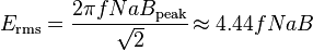
If the flux does not contain even harmonics the following equation can be used for half-cycle average voltage Eavg of any waveshape:

If the flux in the core is purely sinusoidal, the relationship for either winding between its rms voltage Erms of the winding , and the supply frequency f, number of turns N, core cross-sectional area a and peak magnetic flux density B is given by the universal EMF equation:[31]
If the flux does not contain even harmonics the following equation can be used for half-cycle average voltage Eavg of any waveshape:
The time-derivative term in Faraday's Law shows that the flux in the core is the integral with respect to time of the applied voltage.[36] Hypothetically an ideal transformer would work with direct-current excitation, with the core flux increasing linearly with time.[37] In practice, the flux would rise to the point where magnetic saturation of the core occurs, causing a huge increase in the magnetizing current and overheating the transformer. All practical transformers must therefore operate with alternating (or pulsed) current.[37]
The EMF of a transformer at a given flux density increases with frequency.[31] By operating at higher frequencies, transformers can be physically more compact because a given core is able to transfer more power without reaching saturation and fewer turns are needed to achieve the same impedance. However, properties such as core loss and conductor skin effect also increase with frequency. Aircraft and military equipment employ 400 Hz power supplies which reduce core and winding weight.[38] Conversely, frequencies used for some railway electrification systems were much lower (e.g. 16.7 Hz and 25 Hz) than normal utility frequencies (50 – 60 Hz) for historical reasons concerned mainly with the limitations of early electric traction motors. As such, the transformers used to step down the high over-head line voltages (e.g. 15 kV) are much heavier for the same power rating than those designed only for the higher frequencies.
Operation of a transformer at its designed voltage but at a higher frequency than intended will lead to reduced magnetizing current; at lower frequency, the magnetizing current will increase. Operation of a transformer at other than its design frequency may require assessment of voltages, losses, and cooling to establish if safe operation is practical. For example, transformers may need to be equipped with "volts per hertz" over-excitation relays to protect the transformer from overvoltage at higher than rated frequency.
One example of state-of-the-art design is those transformers used for electric multiple unit high speed trains, particularly those required to operate across the borders of countries using different standards of electrification. The position of such transformers is restricted to being hung below the passenger compartment. They have to function at different frequencies (down to 16.7 Hz) and voltages (up to 25 kV) whilst handling the enhanced power requirements needed for operating the trains at high speed.
Knowledge of natural frequencies of transformer windings is of importance for the determination of the transient response of the windings to impulse and switching surge voltages.
Energy losses
An ideal transformer would have no energy losses, and would be 100% efficient. In practical transformers energy is dissipated in the windings, core, and surrounding structures. Larger transformers are generally more efficient, and those rated for electricity distribution usually perform better than 98%.[39]
Experimental transformers using superconducting windings achieve efficiencies of 99.85%.[40] The increase in efficiency can save considerable energy, and hence money, in a large heavily-loaded transformer; the trade-off is in the additional initial and running cost of the superconducting design.
Losses in transformers (excluding associated circuitry) vary with load current, and may be expressed as "no-load" or "full-load" loss. Winding resistance dominates load losses, whereas hysteresis and eddy currents losses contribute to over 99% of the no-load loss. The no-load loss can be significant, so that even an idle transformer constitutes a drain on the electrical supply and a running cost; designing transformers for lower loss requires a larger core, good-quality silicon steel, or even amorphous steel, for the core, and thicker wire, increasing initial cost, so that there is a trade-off between initial cost and running cost. (Also see energy efficient transformer).[41]
Transformer losses are divided into losses in the windings, termed copper loss, and those in the magnetic circuit, termed iron loss. Losses in the transformer arise from:
- Winding resistance
- Current flowing through the windings causes resistive heating of the conductors. At higher frequencies, skin effect and proximity effect create additional winding resistance and losses.
- Hysteresis losses
- Each time the magnetic field is reversed, a small amount of energy is lost due to hysteresis within the core. For a given core material, the loss is proportional to the frequency, and is a function of the peak flux density to which it is subjected.[41]
- Eddy currents
- Ferromagnetic materials are also good conductors, and a core made from such a material also constitutes a single short-circuited turn throughout its entire length. Eddy currents therefore circulate within the core in a plane normal to the flux, and are responsible for resistive heating of the core material. The eddy current loss is a complex function of the square of supply frequency and inverse square of the material thickness.[41] Eddy current losses can be reduced by making the core of a stack of plates electrically insulated from each other, rather than a solid block; all transformers operating at low frequencies use laminated or similar cores.
- Magnetostriction
- Magnetic flux in a ferromagnetic material, such as the core, causes it to physically expand and contract slightly with each cycle of the magnetic field, an effect known as magnetostriction. This produces the buzzing sound commonly associated with transformers,[30] and can cause losses due to frictional heating.
- Mechanical losses
- In addition to magnetostriction, the alternating magnetic field causes fluctuating forces between the primary and secondary windings. These incite vibrations within nearby metalwork, adding to the buzzing noise, and consuming a small amount of power.[42]
- Stray losses
- Leakage inductance is by itself largely lossless, since energy supplied to its magnetic fields is returned to the supply with the next half-cycle. However, any leakage flux that intercepts nearby conductive materials such as the transformer's support structure will give rise to eddy currents and be converted to heat.[43] There are also radiative losses due to the oscillating magnetic field, but these are usually small.
Dot convention
Main article: Dot convention
It is common in transformer schematic symbols for there to be a dot at the end of each coil within a transformer, particularly for transformers with multiple primary and secondary windings. The dots indicate the direction of each winding relative to the others. Voltages at the dot end of each winding are in phase; current flowing into the dot end of a primary coil will result in current flowing out of the dot end of a secondary coil.
Equivalent circuit
- Refer to the diagram below
The physical limitations of the practical transformer may be brought together as an equivalent circuit model (shown below) built around an ideal lossless transformer.[44] Power loss in the windings is current-dependent and is represented as in-series resistances Rp and Rs. Flux leakage results in a fraction of the applied voltage dropped without contributing to the mutual coupling, and thus can be modeled as reactances of each leakage inductance Xp and Xs in series with the perfectly coupled region.
Iron losses are caused mostly by hysteresis and eddy current effects in the core, and are proportional to the square of the core flux for operation at a given frequency.[45] Since the core flux is proportional to the applied voltage, the iron loss can be represented by a resistance RC in parallel with the ideal transformer.
A core with finite permeability requires a magnetizing current Im to maintain the mutual flux in the core. The magnetizing current is in phase with the flux; saturation effects cause the relationship between the two to be non-linear, but for simplicity this effect tends to be ignored in most circuit equivalents.[45] With a sinusoidal supply, the core flux lags the induced EMF by 90° and this effect can be modeled as a magnetizing reactance (reactance of an effective inductance) Xm in parallel with the core loss component. Rc and Xm are sometimes together termed the magnetizing branch of the model. If the secondary winding is made open-circuit, the current I0 taken by the magnetizing branch represents the transformer's no-load current.[44]
The secondary impedance Rs and Xs is frequently moved (or "referred") to the primary side after multiplying the components by the impedance scaling factor (Np/Ns)2.
Transformer equivalent circuit, with secondary impedances referred to the primary side
The resulting model is sometimes termed the "exact equivalent circuit", though it retains a number of approximations, such as an assumption of linearity.[44] Analysis may be simplified by moving the magnetizing branch to the left of the primary impedance, an implicit assumption that the magnetizing current is low, and then summing primary and referred secondary impedances, resulting in so-called equivalent impedance.
The parameters of equivalent circuit of a transformer can be calculated from the results of two transformer tests: open-circuit test and short-circuit test.
Autotransformer
Main article: Autotransformer
In an autotransformer portions of the same winding act as both the primary and secondary. The winding has at least three taps where electrical connections are made. An autotransformer can be smaller, lighter and cheaper than a standard dual-winding transformer however the autotransformer does not provide electrical isolation.
Autotransformers are often used to step up or down between voltages in the 110-117-120 volt range and voltages in the 220-230-240 volt range, e.g., to output either 110 or 120V (with taps) from 230V input, allowing equipment from a 100 or 120V region to be used in a 230V region.
A variable autotransformer is made by exposing part of the winding coils and making the secondary connection through a sliding brush, giving a variable turns ratio.[46] Such a device is often referred to by the trademark name variac.
Polyphase transformers
For more details on this topic, see Three-phase electric power.
For three-phase supplies, a bank of three individual single-phase transformers can be used, or all three phases can be incorporated as a single three-phase transformer. In this case, the magnetic circuits are connected together, the core thus containing a three-phase flow of flux.[47] A number of winding configurations are possible, giving rise to different attributes and phase shifts.[48] One particular polyphase configuration is the zigzag transformer, used for grounding and in the suppression of harmonic currents.[49]
Screenshot of a FEM simulation of the magnetic flux inside a three-phase power transformer. Full animation is available too.
Leakage transformers

Leakage transformer
A leakage transformer, also called a stray-field transformer, has a significantly higher leakage inductance than other transformers, sometimes increased by a magnetic bypass or shunt in its core between primary and secondary, which is sometimes adjustable with a set screw. This provides a transformer with an inherent current limitation due to the loose coupling between its primary and the secondary windings. The output and input currents are low enough to prevent thermal overload under all load conditions—even if the secondary is shorted.
Leakage transformers are used for arc welding and high voltage discharge lamps (neon lights and cold cathode fluorescent lamps, which are series-connected up to 7.5 kV AC). It acts then both as a voltage transformer and as a magnetic ballast.
Other applications are short-circuit-proof extra-low voltage transformers for toys or doorbell installations.
Resonant transformers
For more details on this topic, see Resonant inductive coupling.
A resonant transformer is a kind of leakage transformer. It uses the leakage inductance of its secondary windings in combination with external capacitors, to create one or more resonant circuits. Resonant transformers such as the Tesla coil can generate very high voltages, and are able to provide much higher current than electrostatic high-voltage generation machines such as the Van de Graaff generator.[50] One of the applications of the resonant transformer is for the CCFL inverter. Another application of the resonant transformer is to couple between stages of a superheterodyne receiver, where the selectivity of the receiver is provided by tuned transformers in the intermediate-frequency amplifiers.[51]
Audio transformers
Audio transformers are those specifically designed for use in audio circuits. They can be used to block radio frequency interference or the DC component of an audio signal, to split or combine audio signals, or to provide impedance matching between high and low impedance circuits, such as between a high impedance tube (valve) amplifier output and a low impedance loudspeaker, or between a high impedance instrument output and the low impedance input of a mixing console.
Such transformers were originally designed to connect different telephone systems to one another while keeping their respective power supplies isolated, and are still commonly used to interconnect professional audio systems or system components.
Being magnetic devices, audio transformers are susceptible to external magnetic fields such as those generated by AC current-carrying conductors. "Hum" is a term commonly used to describe unwanted signals originating from the "mains" power supply (typically 50 or 60 Hz). Audio transformers used for low-level signals, such as those from microphones, often include shielding to protect against extraneous magnetically coupled signals.
Instrument transformers
Instrument transformers are used for measuring voltage and current in electrical power systems, and for power system protection and control. Where a voltage or current is too large to be conveniently used by an instrument, it can be scaled down to a standardized, low value. Instrument transformers isolate measurement, protection and control circuitry from the high currents or voltages present on the circuits being measured or controlled.

Current transformers, designed for placing around conductors
A current transformer is a transformer designed to provide a current in its secondary coil proportional to the current flowing in its primary coil.[52]
Voltage transformers (VTs), also referred to as "potential transformers" (PTs), are designed to have an accurately known transformation ratio in both magnitude and phase, over a range of measuring circuit impedances. A voltage transformer is intended to present a negligible load to the supply being measured. The low secondary voltage allows protective relay equipment and measuring instruments to be operated at a lower voltages.[53]
Both current and voltage instrument transformers are designed to have predictable characteristics on overloads. Proper operation of over-current protective relays requires that current transformers provide a predictable transformation ratio even during a short-circuit.
Classification
Transformers can be considered a class of electric machine with no moving parts; as such they are described as static electric machines. They can be classified in many different ways; an incomplete list is:
- By power capacity: from a fraction of a volt-ampere (VA) to over a thousand MVA;
- By frequency range: power-, audio-, or radio frequency;
- By voltage class: from a few volts to hundreds of kilovolts;
- By cooling type: air-cooled, oil-filled, fan-cooled, or water-cooled;
- By application: such as power supply, impedance matching, output voltage and current stabilizer, or circuit isolation;
- By purpose: distribution, rectifier, arc furnace, amplifier output, etc.;
- By winding turns ratio: step-up, step-down, isolating with equal or near-equal ratio, variable, multiple windings.
Construction
Cores
Transformers for use at power or audio frequencies typically have cores made of high permeability silicon steel.[54] The steel has a permeability many times that of free space, and the core thus serves to greatly reduce the magnetizing current, and confine the flux to a path which closely couples the windings.[55] Early transformer developers soon realized that cores constructed from solid iron resulted in prohibitive eddy-current losses, and their designs mitigated this effect with cores consisting of bundles of insulated iron wires.[8] Later designs constructed the core by stacking layers of thin steel laminations, a principle that has remained in use. Each lamination is insulated from its neighbors by a thin non-conducting layer of insulation.[47] The universal transformer equation indicates a minimum cross-sectional area for the core to avoid saturation.
The effect of laminations is to confine eddy currents to highly elliptical paths that enclose little flux, and so reduce their magnitude. Thinner laminations reduce losses,[54] but are more laborious and expensive to construct.[56] Thin laminations are generally used on high frequency transformers, with some types of very thin steel laminations able to operate up to 10 kHz.

Laminating the core greatly reduces eddy-current losses
One common design of laminated core is made from interleaved stacks of E-shaped steel sheets capped with I-shaped pieces, leading to its name of "E-I transformer".[56] Such a design tends to exhibit more losses, but is very economical to manufacture. The cut-core or C-core type is made by winding a steel strip around a rectangular form and then bonding the layers together. It is then cut in two, forming two C shapes, and the core assembled by binding the two C halves together with a steel strap.[56] They have the advantage that the flux is always oriented parallel to the metal grains, reducing reluctance.
A steel core's remanence means that it retains a static magnetic field when power is removed. When power is then reapplied, the residual field will cause a high inrush current until the effect of the remaining magnetism is reduced, usually after a few cycles of the applied alternating current.[57] Overcurrent protection devices such as fuses must be selected to allow this harmless inrush to pass. On transformers connected to long, overhead power transmission lines, induced currents due to geomagnetic disturbances during solar storms can cause saturation of the core and operation of transformer protection devices.[58]
Distribution transformers can achieve low no-load losses by using cores made with low-loss high-permeability silicon steel or amorphous (non-crystalline) metal alloy. The higher initial cost of the core material is offset over the life of the transformer by its lower losses at light load.[59]
Solid cores
Powdered iron cores are used in circuits (such as switch-mode power supplies) that operate above main frequencies and up to a few tens of kilohertz. These materials combine high magnetic permeability with high bulk electrical resistivity. For frequencies extending beyond the VHF band, cores made from non-conductive magnetic ceramic materials called ferrites are common.[56] Some radio-frequency transformers also have movable cores (sometimes called 'slugs') which allow adjustment of the coupling coefficient (and bandwidth) of tuned radio-frequency circuits.
Toroidal cores
Small toroidal core transformer
Toroidal transformers are built around a ring-shaped core, which, depending on operating frequency, is made from a long strip of silicon steel or permalloy wound into a coil, powdered iron, or ferrite.[60] A strip construction ensures that the grain boundaries are optimally aligned, improving the transformer's efficiency by reducing the core's reluctance. The closed ring shape eliminates air gaps inherent in the construction of an E-I core.[35] The cross-section of the ring is usually square or rectangular, but more expensive cores with circular cross-sections are also available. The primary and secondary coils are often wound concentrically to cover the entire surface of the core. This minimizes the length of wire needed, and also provides screening to minimize the core's magnetic field from generating electromagnetic interference.
Toroidal transformers are more efficient than the cheaper laminated E-I types for a similar power level. Other advantages compared to E-I types, include smaller size (about half), lower weight (about half), less mechanical hum (making them superior in audio amplifiers), lower exterior magnetic field (about one tenth), low off-load losses (making them more efficient in standby circuits), single-bolt mounting, and greater choice of shapes. The main disadvantages are higher cost and limited power capacity (see "Classification" above). Because of the lack of a residual gap in the magnetic path, toroidal transformers also tend to exhibit higher inrush current, compared to laminated E-I types.
Ferrite toroidal cores are used at higher frequencies, typically between a few tens of kilohertz to hundreds of megahertz, to reduce losses, physical size, and weight of switch-mode power supplies. A drawback of toroidal transformer construction is the higher labor cost of winding. This is because it is necessary to pass the entire length of a coil winding through the core aperture each time a single turn is added to the coil. As a consequence, toroidal transformers are uncommon above ratings of a few kVA. Small distribution transformers may achieve some of the benefits of a toroidal core by splitting it and forcing it open, then inserting a bobbin containing primary and secondary windings.
Air cores
A physical core is not an absolute requisite and a functioning transformer can be produced simply by placing the windings near each other, an arrangement termed an "air-core" transformer. The air which comprises the magnetic circuit is essentially lossless, and so an air-core transformer eliminates loss due to hysteresis in the core material.[33] The leakage inductance is inevitably high, resulting in very poor regulation, and so such designs are unsuitable for use in power distribution.[33] They have however very high bandwidth, and are frequently employed in radio-frequency applications,[61] for which a satisfactory coupling coefficient is maintained by carefully overlapping the primary and secondary windings. They're also used for resonant transformers such as Tesla coils where they can achieve reasonably low loss in spite of the high leakage inductance.
Windings
Windings are usually arranged concentrically to minimize flux leakage.
Cut view through transformer windings. White: insulator. Green spiral: Grain oriented silicon steel. Black: Primary winding made of oxygen-free copper. Red: Secondary winding. Top left: Toroidal transformer. Right: C-core, but E-core would be similar. The black windings are made of film. Top: Equally low capacitance between all ends of both windings. Since most cores are at least moderately conductive they also need insulation. Bottom: Lowest capacitance for one end of the secondary winding needed for low-power high-voltage transformers. Bottom left: Reduction of leakage inductance would lead to increase of capacitance.
The conducting material used for the windings depends upon the application, but in all cases the individual turns must be electrically insulated from each other to ensure that the current travels throughout every turn.[36] For small power and signal transformers, in which currents are low and the potential difference between adjacent turns is small, the coils are often wound from enamelled magnet wire, such as Formvar wire. Larger power transformers operating at high voltages may be wound with copper rectangular strip conductors insulated by oil-impregnated paper and blocks of pressboard.[62]
High-frequency transformers operating in the tens to hundreds of kilohertz often have windings made of braided Litz wire to minimize the skin-effect and proximity effect losses.[36] Large power transformers use multiple-stranded conductors as well, since even at low power frequencies non-uniform distribution of current would otherwise exist in high-current windings.[62] Each strand is individually insulated, and the strands are arranged so that at certain points in the winding, or throughout the whole winding, each portion occupies different relative positions in the complete conductor. The transposition equalizes the current flowing in each strand of the conductor, and reduces eddy current losses in the winding itself. The stranded conductor is also more flexible than a solid conductor of similar size, aiding manufacture.[62]
For signal transformers, the windings may be arranged in a way to minimize leakage inductance and stray capacitance to improve high-frequency response. This can be done by splitting up each coil into sections, and those sections placed in layers between the sections of the other winding. This is known as a stacked type or interleaved winding.
Both the primary and secondary windings on power transformers may have external connections, called taps, to intermediate points on the winding to allow selection of the voltage ratio. In distribution transformers the taps may be connected to an automatic on-load tap changer for voltage regulation of distribution circuits. Audio-frequency transformers, used for the distribution of audio to public address loudspeakers, have taps to allow adjustment of impedance to each speaker. A center-tapped transformer is often used in the output stage of an audio power amplifier in a push-pull circuit. Modulation transformers in AM transmitters are very similar.
Certain transformers have the windings protected by epoxy resin. By impregnating the transformer with epoxy under a vacuum, one can replace air spaces within the windings with epoxy, thus sealing the windings and helping to prevent the possible formation of corona and absorption of dirt or water. This produces transformers more suited to damp or dirty environments, but at increased manufacturing cost.[63]
Coolant
Cut-away view of three-phase oil-cooled transformer. The oil reservoir is visible at the top. Radiative fins aid the dissipation of heat.
High temperatures will damage the winding insulation.[64] Small transformers do not generate significant heat and are cooled by air circulation and radiation of heat. Power transformers rated up to several hundred kVA can be adequately cooled by natural convective air-cooling, sometimes assisted by fans.[65] In larger transformers, part of the design problem is removal of heat. Some power transformers are immersed in transformer oil that both cools and insulates the windings.[66] The oil is a highly refined mineral oil that remains stable at transformer operating temperature. Indoor liquid-filled transformers are required by building regulations in many jurisdictions to use a non-flammable liquid, or to be located in fire-resistant rooms.[67] Air-cooled dry transformers are preferred for indoor applications even at capacity ratings where oil-cooled construction would be more economical, because their cost is offset by the reduced building construction cost.
The oil-filled tank often has radiators through which the oil circulates by natural convection; some large transformers employ forced circulation of the oil by electric pumps, aided by external fans or water-cooled heat exchangers.[66] Oil-filled transformers undergo prolonged drying processes to ensure that the transformer is completely free of water vapor before the cooling oil is introduced. This helps prevent electrical breakdown under load. Oil-filled transformers may be equipped with Buchholz relays, which detect gas evolved during internal arcing and rapidly de-energize the transformer to avert catastrophic failure.[57] Oil-filled transformers may fail, rupture, and burn, causing power outages and losses. Installations of oil-filled transformers usually includes fire protection measures such as walls, oil containment, and fire-suppression sprinkler systems.
Polychlorinated biphenyls have properties that once favored their use as a coolant, though concerns over their environmental persistence led to a widespread ban on their use.[68] Today, non-toxic, stable silicone-based oils, or fluorinated hydrocarbons may be used where the expense of a fire-resistant liquid offsets additional building cost for a transformer vault.[64][67] Before 1977, even transformers that were nominally filled only with mineral oils may also have been contaminated with polychlorinated biphenyls at 10-20 ppm. Since mineral oil and PCB fluid mix, maintenance equipment used for both PCB and oil-filled transformers could carry over small amounts of PCB, contaminating oil-filled transformers.[69]
Some "dry" transformers (containing no liquid) are enclosed in sealed, pressurized tanks and cooled by nitrogen or sulfur hexafluoride gas.[64]
Experimental power transformers in the 2 MVA range have been built with superconducting windings which eliminates the copper losses, but not the core steel loss. These are cooled by liquid nitrogen or helium
Insulation drying
Construction of oil-filled transformers requires that the insulation covering the windings be thoroughly dried before the oil is introduced. There are several different methods of drying. Common for all is that they are carried out in vacuum environment. The vacuum makes it difficult to transfer energy (heat) to the insulation. For this there are several different methods. The traditional drying is done by circulating hot air over the active part and cycle this with periods of vacuum (hot-air vacuum drying, HAV). More common for larger transformers is to use evaporated solvent which condenses on the colder active part. The benefit is that the entire process can be carried out at lower pressure and without influence of added oxygen. This process is commonly called vapour-phase drying (VPD).
For distribution transformers, which are smaller and have a smaller insulation weight, resistance heating can be used. This is a method where current is injected in the windings to heat the insulation. The benefit is that the heating can be controlled very well and it is energy efficient. The method is called low-frequency heating (LFH) since the current is injected at a much lower frequency than the nominal of the grid, which is normally 50 or 60 Hz. A lower frequency reduces the effect of the inductance in the transformer, so the voltage can be reduced.
Terminals
Very small transformers will have wire leads connected directly to the ends of the coils, and brought out to the base of the unit for circuit connections. Larger transformers may have heavy bolted terminals, bus bars or high-voltage insulated bushings made of polymers or porcelain. A large bushing can be a complex structure since it must provide careful control of the electric field gradient without letting the transformer leak oil.[71]
Applications

A major application of transformers is to increase voltage before transmitting electrical energy over long distances through wires. Wires have resistance and so dissipate electrical energy at a rate proportional to the square of the current through the wire. By transforming electrical power to a high-voltage (and therefore low-current) form for transmission and back again afterward, transformers enable economical transmission of power over long distances. Consequently, transformers have shaped the electricity supply industry, permitting generation to be located remotely from points of demand.[72] All but a tiny fraction of the world's electrical power has passed through a series of transformers by the time it reaches the consumer.[43]
Transformers are also used extensively in electronic products to step down the supply voltage to a level suitable for the low voltage circuits they contain. The transformer also electrically isolates the end user from contact with the supply voltage.
Signal and audio transformers are used to couple stages of amplifiers and to match devices such as microphones and record players to the input of amplifiers. Audio transformers allowed telephone circuits to carry on a two-way conversation over a single pair of wires. A balun transformer converts a signal that is referenced to ground to a signal that has balanced voltages to ground, such as between external cables and internal circuits.
The principle of open-circuit (unloaded) transformer is widely used for characterisation of soft magnetic materials, for example in the internationally standardised Epstein frame method
Toroidal inductors and transformers
From Wikipedia, the free encyclopedia
 |  | |
Several small toroidal inductors. The major scale is in inches. | A small toroidal transformer. |
Toroidal inductors and transformers are electronic components, typically consisting of a circular ring-shaped magnetic core of iron powder, ferrite, or other material around which wire is coiled to make an inductor. Toroidal coils are used in a broad range of applications, such as high-frequency coils and transformers. Toroidal inductors can have higher Q factors and higher inductance than similarly constructed solenoid coils. This is due largely to the smaller number of turns required when the core provides a closed magnetic path. The magnetic flux in a high permeability toroid is largely confined to the core; the confinement reduces the energy that can be absorbed by nearby objects, so toroidal cores offer some self-shielding.
In the geometry of torus-shaped magnetic fields, the poloidal flux direction threads the "donut hole" in the center of the torus, while the toroidal flux direction is parallel the core of the torus.
Total B Field Confinement by Toroidal Inductors
In some circumstance, the current in the winding of a toroidal inductor contributes only to the B field inside the windings and makes no contribution to the magnetic B field outside of the windings.
Sufficient conditions for total internal confinement of the B field
  Fig.1.Coordinate system. The Z axis is the nominal axis of symmetry. The X axis chosen arbitrarily to line up with the starting point of the winding. ρ is called the radial direction. θ is called the circumferential direction. Fig.1.Coordinate system. The Z axis is the nominal axis of symmetry. The X axis chosen arbitrarily to line up with the starting point of the winding. ρ is called the radial direction. θ is called the circumferential direction. |
The absence of circumferential current [1] (please refer to figure 1 of this section for definition of directions) and the axially symmetric layout of the conductors and magnetic materials [1][2][3] are sufficient conditions for total internal confinement of the B field. (Some authors prefer to use the H field). Because of the symmetry, the lines of B flux must form circles of constant intensity centered on the axis of symmetry. The only lines of B flux that encircle any current are those that are inside the toroidal winding. Therefore, from Ampere's circuital law, the intensity of the B field must be zero outside the windings.[3]

Figure 3 of this section shows the most common toroidal winding. It fails both requirements for total B field confinement. Looking out from the axis, sometimes the winding is on the inside of the core and sometimes it is on the outside of the core. It is not axially symmetric in the near region. However, at points a distance of several times the winding spacing, the toroid does look symmetric[4]. There is still the problem of the circumferential current. No matter how many times the winding encircles the core and no matter how thin the wire, this toroidal inductor will function as a one coil loop in the plane of the toroid. This winding will also produce and be susceptible to an E field in the plane of the inductor.
Figures 4-6 show different ways to neutralize the circumferential current. Figure 4 is the simplest and has the advantage that the return wire can be added after the inductor is bought or built.


 Fig. 4. Circumferential current countered with a return wire. The wire is white and runs between the outer rim of the inductor and the outer portion of the winding.
] E Field in the Plane of the Toroid


There will be a distribution of potential along the winding. This can lead to an E-Field in the plane of the toroid and also a susceptibility to an E field in the plane of the toroid as shown in figure 7. This can be mitigated by using a return winding as shown on figure 8. With this winding, each place the winding crosses itself, the two parts will be at equal and opposite polarity which substantially reduces the E field generated in the plane.
Torroidal Inductor/Transformer and Magnetic Vector Potential
Main article: Magnetic potential

Showing the development of the magnetic vector potential around a symmetric torroidal inductor.
See Feynman chapter 14[5] and 15[6] for a general discussion of magnetic vector potential. See Feynman page 15-11 [7] for a diagram of the magnetic vector potential around a long thin solenoid which also exhibits total internal confinement of the B field, at least in the infinite limit.
The A field is accurate when using the assumption bfA = 0. This would be true under the following assumptions:
- 1. the Coulomb gauge is used
- 2. the Lorenz gauge is used and there is no distribution of charge,

- 3. the Lorenz gauge is used and zero frequency is assumed
- 4. the Lorenz gauge is used and a non-zero frequency that is low enough to neglect
 is assumed.
Number 4 will be presumed for the rest of this section and may be referred to the "quasi-static condition".
Although the axially symmetric toroidal inductor with no circumferential current totally confines the B field within the windings, the A field (magnetic vector potential) is not confined. Arrow #1 in the picture depicts the vector potential on the axis of symmetry. Radial current sections a and b are equal distances from the axis but pointed in opposite directions, so they will cancel. Likewise segments c and d cancel. In fact all the radial current segments cancel. The situation for axial currents is different. The axial current on the outside of the toroid is pointed down and the axial current on the inside of the toroid is pointed up. Each axial current segment on the outside of the toroid can be matched with an equal but oppositely directed segment on the inside of the toroid. The segments on the inside are closer than the segments on the outside to the axis, therefore there is a net upward component of the A field along the axis of symmetry.

Representing the magnetic vector potential (A), magnetic flux (B), and current density (j) fields around a toroidal inductor of circular cross section. Thicker lines indicate field lines of higher average intensity. Circles in cross section of the core represent B flux coming out of the picture. Plus signs on the other cross section of the core represent B flux going into the picture. Div A = 0 has been assumed.
Since the equations  , and
, and  (assuming quasi-static conditions, i.e.
  ) have the same form, then the lines and contours of A relate to B like the lines and contours of B relate to j. Thus, a depiction of the A field around a loop of B flux (as would be produced in a toroidal inductor) is qualitatively the same as the B field around a loop of current. The figure to the left is an artist's depiction of the A field around a totoidal inductor. The thicker lines indicate paths of higher average intensity (shorter paths have higher intensity so that the path integral is the same). The lines are just drawn to look good and impart general look of the A field.
, and (assuming quasi-static conditions, i.e. ) have the same form, then the lines and contours of A relate to B like the lines and contours of B relate to j. Thus, a depiction of the A field around a loop of B flux (as would be produced in a toroidal inductor) is qualitatively the same as the B field around a loop of current. The figure to the left is an artist's depiction of the A field around a totoidal inductor. The thicker lines indicate paths of higher average intensity (shorter paths have higher intensity so that the path integral is the same). The lines are just drawn to look good and impart general look of the A field.[edit] Toroidal Transformer Action in the Presence of Total B field Confinement
The E and B fields can be computed from the A and  (scalar electric potential) fields
(scalar electric potential) fields [8] and :
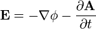 [8] and so even if the region outside the windings is devoid of B field, it is filled with non-zero E field.
- The quantity
 is responsible for the desirable magnetic field coupling between primary and secondary while the quantity
  is responsible for the undesirable electric field coupling between primary and secondary. Transformer designers attempt to minimize the electric field coupling. For the rest of this section, will assumed to be zero unless otherwise specified.
Stokes theorem applies[9], so that the path integral of A is equal to the enclosed B flux, just as the path integral B is equal to a constant times the enclosed current
The path integral of E along the secondary winding gives the secondary's induced EMF (Electro-Motive Force).

which says the EMF is equal to the time rate of change of the B flux enclosed by the winding, which is the usual result.
[edit] Toroidal Transformer Poynting Vector Coupling from Primary to Secondary in the Presence of Total B field Confinement
Explanation of the Figure
This figure shows the half section of a toroidal transformer. Quasi-static conditions are assumed, so the phase of each field is everywhere the same. The transformer, its windings and all things are distributed symmetrically about the axis of symmetry. The windings are such that there is no circumferential current. The requirements are met for full internal confinement of the B field due to the primary current. The core and primary winding are represented by the gray-brown torus. The primary winding is not shown, but the current in the winding at the cross section surface is shown as gold (or orange) ellipses. The B field caused by the primary current is entirely confined to the region enclosed by the primary winding (i.e. the core). Blue dots on the left hand cross section indicate that lines of B flux in the core come out of the left hand cross section. On the other cross section, blue plus signs indicate that the B flux enters there. The E field sourced from the primary currents is shown as green ellipses. The secondary winding is shown as a brown line coming directly down the axis of symmetry. In normal practice, the two ends of the secondary are connected together with a long wire that stays well away from the torus, but to maintain the absolute axial symmetry, the entire apparatus is envisioned as being inside a perfectly conductive sphere with the secondary wire "grounded" to the inside of the sphere at each end. The secondary is made of resistance wire, so there is no separate load. The E field along the secondary causes current in the secondary (yellow arrows) which causes a B field around the secondary (shown as blue ellipses). This B field fills space, including inside the transformer core, so in the end, there is continuous non-zero B field from the primary to the secondary, if the secondary is not open circuited. The cross product of the E field (sourced from primary currents) and the B field (sourced from the secondary currents) forms the Poynting vector which points from the primary toward the secondary.

thanks sir for great info but iam confuse in transformer formula can u please explain more on easy steps like some more on inverter transformer please!
ReplyDelete