Principles of operation
In any electric motor, operation is based on simple electromagnetism. A current-carrying conductor generates a magnetic field; when this is then placed in an external magnetic field, it will experience a force proportional to the current in the conductor, and to the strength of the external magnetic field. As you are well aware of from playing with magnets as a kid, opposite (North and South) polarities attract, while like polarities (North and North, South and South) repel. The internal configuration of a DC motor is designed to harness the magnetic interaction between a current-carrying conductor and an external magnetic field to generate rotational motion.
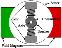
Let's start by looking at a simple 2-pole DC electric motor (here red represents a magnet or winding with a "North" polarization, while green represents a magnet or winding with a "South" polarization).
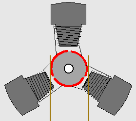
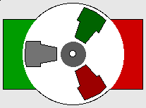
So since most small DC motors are of a three-pole design, let's tinker with the workings of one via an interactive animation (JavaScript required):
The use of an iron core armature (as in the Mabuchi, above) is quite common, and has a number of advantages2. First off, the iron core provides a strong, rigid support for the windings -- a particularly important consideration for high-torque motors. The core also conducts heat away from the rotor windings, allowing the motor to be driven harder than might otherwise be the case. Iron core construction is also relatively inexpensive compared with other construction types.
But iron core construction also has several disadvantages. The iron armature has a relatively high inertia which limits motor acceleration. This construction also results in high winding inductances which limit brush and commutator life.
In small motors, an alternative design is often used which features a 'coreless' armature winding. This design depends upon the coil wire itself for structural integrity. As a result, the armature is hollow, and the permanent magnet can be mounted inside the rotor coil. Coreless DC motors have much lower armature inductance than iron-core motors of comparable size, extending brush and commutator life.
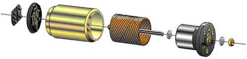
Diagram courtesy of MicroMo
To get the best from DC motors in BEAMbots, we'll need to take a closer look at DC motor behaviors -- both obvious and not.
This is an active graphic. Click on bold type for further illustration. 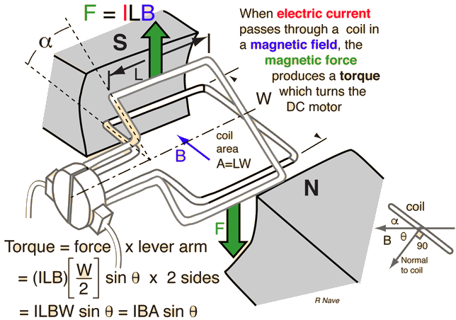
 DC motor design generates an oscillating current in a wound rotor, or armature, with a split ring commutator, and either a wound or permanent magnet stator. A rotor consists of one or more coils of wire wound around a core on a shaft; an electrical power source is connected to the rotor coil through the commutator and its brushes, causing current to flow in it, producing electromagnetism. The commutator causes the current in the coils to be switched as the rotor turns, keeping the magnetic poles of the rotor from ever fully aligning with the magnetic poles of the stator field, so that the rotor never stops (like a compass needle does) but rather keeps rotating indefinitely (as long as power is applied and is sufficient for the motor to overcome the shaft torque load and internal losses due to friction, etc.)
Many of the limitations of the classic commutator DC motor are due to the need for brushes to press against the commutator. This creates friction. Sparks are created by the brushes making and breaking circuits through the rotor coils as the brushes cross the insulating gaps between commutator sections. Depending on the commutator design, this may include the brushes shorting together adjacent sections—and hence coil ends—momentarily while crossing the gaps. Furthermore, the inductance of the rotor coils causes the voltage across each to rise when its circuit is opened, increasing the sparking of the brushes. This sparking limits the maximum speed of the machine, as too-rapid sparking will overheat, erode, or even melt the commutator. The current density per unit area of the brushes, in combination with their resistivity, limits the output of the motor. The making and breaking of electric contact also causes electrical noise, and the sparks additionally cause RFI. Brushes eventually wear out and require replacement, and the commutator itself is subject to wear and maintenance (on larger motors) or replacement (on small motors). The commutator assembly on a large motor is a costly element, requiring precision assembly of many parts. On small motors, the commutator is usually permanently integrated into the rotor, so replacing it usually requires replacing the whole rotor.
Large brushes are desired for a larger brush contact area to maximize motor output, but small brushes are desired for low mass to maximize the speed at which the motor can run without the brushes excessively bouncing and sparking (comparable to the problem of "valve float" in internal combustion engines). (Small brushes are also desirable for lower cost.) Stiffer brush springs can also be used to make brushes of a given mass work at a higher speed, but at the cost of greater friction losses (lower efficiency) and accelerated brush and commutator wear. Therefore, DC motor brush design entails a trade-off between output power, speed, and efficiency/wear.
 There are five types of brushed DC motor:
Because the rotor is much lighter in weight (mass) than a conventional rotor formed from copper windings on steel laminations, the rotor can accelerate much more rapidly, often achieving a mechanical time constant under 1 ms. This is especially true if the windings use aluminum rather than the heavier copper. But because there is no metal mass in the rotor to act as a heat sink, even small coreless motors must often be cooled by forced air.
Related limited-travel actuators have no core and a bonded coil placed between the poles of high-flux thin permanent magnets. These are the fast head positioners for rigid-disk ("hard disk") drives.
 A series-wound motor is referred to as a universal motor when it has been designed to operate on either AC or DC power. The ability to operate on AC is because the current in both the field and the armature (and hence the resultant magnetic fields) will alternate (reverse polarity) in synchronism, and hence the resulting mechanical force will occur in a constant direction.
Operating at normal power line frequencies, universal motors are often found in a range rarely larger than 1000 watt. Universal motors also form the basis of the traditional railway traction motor in electric railways. In this application, the use of AC to power a motor originally designed to run on DC would lead to efficiency losses due to eddy current heating of their magnetic components, particularly the motor field pole-pieces that, for DC, would have used solid (un-laminated) iron. Although the heating effects are reduced by using laminated pole-pieces, as used for the cores of transformers and by the use of laminations of high permeability electrical steel, one solution available at start of the 20th century was for the motors to be operated from very low frequency AC supplies, with 25 and 16.7 Hz operation being common. Because they used universal motors, locomotives using this design were also commonly capable of operating from a third rail powered by DC.
An advantage of the universal motor is that AC supplies may be used on motors which have some characteristics more common in DC motors, specifically high starting torque and very compact design if high running speeds are used. The negative aspect is the maintenance and short life problems caused by the commutator. Such motors are used in devices such as food mixers and power tools which are used only intermittently, and often have high starting-torque demands. Continuous speed control of a universal motor running on AC is easily obtained by use of a thyristor circuit, while multiple taps on the field coil provide (imprecise) stepped speed control. Household blenders that advertise many speeds frequently combine a field coil with several taps and a diode that can be inserted in series with the motor (causing the motor to run on half-wave rectified AC).
Induction motors can't turn a shaft faster than allowed by the power line frequency. By contrast, universal motors generally run at high speeds, making them useful for appliances such as blenders, vacuum cleaners, and hair dryers where high speed and light weight is desirable. They are also commonly used in portable power tools, such as drills, sanders, circular and jig saws, where the motor's characteristics work well. Many vacuum cleaner and weed trimmer motors exceed 10,000 RPM, while Dremel and other similar miniature grinders will often exceed 30,000 RPM.
Universal motors also lend themselves to electronic speed control and, as such, are an ideal choice for domestic washing machines. The motor can be used to agitate the drum (both forwards and in reverse) by switching the field winding with respect to the armature. The motor can also be run up to the high speeds required for the spin cycle.
Motor damage may occur from overspeeding (running at an rotational speed in excess of design limits) if the unit is operated with no significant load. On larger motors, sudden loss of load is to be avoided, and the possibility of such an occurrence is incorporated into the motor's protection and control schemes. In some smaller applications, a fan blade attached to the shaft often acts as an artificial load to limit the motor speed to a safe level, as well as a means to circulate cooling airflow over the armature and field windings.
And for a linear motor:
 ,
,
where η is energy conversion efficiency, Pe is electrical input power, and Pm is mechanical output power.
In simplest case Pe = VI, and Pm = Tω, where V is input voltage, I is input current, T is output torque, and ω is output angular velocity. It is possible to derive analytically the point of maximum efficiency. It is typically at less than 1/2 the stall torque.

Where:
In any electric motor, operation is based on simple electromagnetism. A current-carrying conductor generates a magnetic field; when this is then placed in an external magnetic field, it will experience a force proportional to the current in the conductor, and to the strength of the external magnetic field. As you are well aware of from playing with magnets as a kid, opposite (North and South) polarities attract, while like polarities (North and North, South and South) repel. The internal configuration of a DC motor is designed to harness the magnetic interaction between a current-carrying conductor and an external magnetic field to generate rotational motion.
Let's start by looking at a simple 2-pole DC electric motor (here red represents a magnet or winding with a "North" polarization, while green represents a magnet or winding with a "South" polarization).
| The geometry of the brushes, commutator contacts, and rotor windings are such that when power is applied, the polarities of the energized winding and the stator magnet(s) are misaligned, and the rotor will rotate until it is almost aligned with the stator's field magnets. As the rotor reaches alignment, the brushes move to the next commutator contacts, and energize the next winding. Given our example two-pole motor, the rotation reverses the direction of current through the rotor winding, leading to a "flip" of the rotor's magnetic field, driving it to continue rotating. In real life, though, DC motors will always have more than two poles (three is a very common number). In particular, this avoids "dead spots" in the commutator. You can imagine how with our example two-pole motor, if the rotor is exactly at the middle of its rotation (perfectly aligned with the field magnets), it will get "stuck" there. Meanwhile, with a two-pole motor, there is a moment where the commutator shorts out the power supply (i.e., both brushes touch both commutator contacts simultaneously). This would be bad for the power supply, waste energy, and damage motor components as well. Yet another disadvantage of such a simple motor is that it would exhibit a high amount of torque "ripple" (the amount of torque it could produce is cyclic with the position of the rotor). | 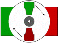 |
 |
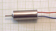
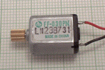 | There's probably no better way to see how an average DC motor is put together, than by just opening one up. Unfortunately this is tedious work, as well as requiring the destruction of a perfectly good motor. Luckily for you, I've gone ahead and done this in your stead. The guts of a disassembled Mabuchi FF-030-PN motor (the same model that Solarbotics sells) are available for you to see here (on 10 lines / cm graph paper). This is a basic 3-pole DC motor, with 2 brushes and three commutator contacts. |
But iron core construction also has several disadvantages. The iron armature has a relatively high inertia which limits motor acceleration. This construction also results in high winding inductances which limit brush and commutator life.
In small motors, an alternative design is often used which features a 'coreless' armature winding. This design depends upon the coil wire itself for structural integrity. As a result, the armature is hollow, and the permanent magnet can be mounted inside the rotor coil. Coreless DC motors have much lower armature inductance than iron-core motors of comparable size, extending brush and commutator life.
Diagram courtesy of MicroMo
 | Again, disassembling a coreless motor can be instructive -- in this case, my hapless victim was a cheap pager vibrator motor. The guts of this disassembled motor are available for you to see here (on 10 lines / cm graph paper). This is (or more accurately, was) a 3-pole coreless DC motor. I disembowel 'em so you don't have to... |
DC Motor Operation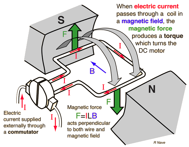
| Index Magnetic field concepts Magnetic force applications | |
| HyperPhysics***** Electricity and Magnetism | Go Back |
Current in DC Motor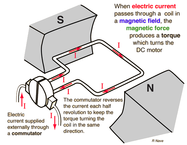
| Index Magnetic field concepts Magnetic force applications | |
| HyperPhysics***** Electricity and Magnetism | Go Back |
Magnetic Field in DC Motor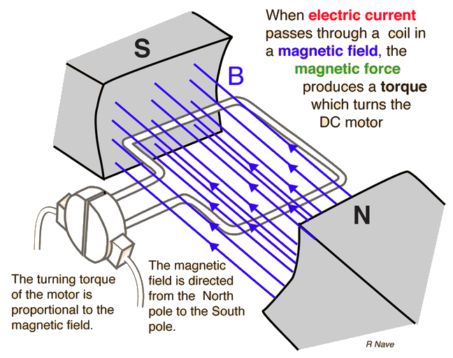
| Index Magnetic field concepts Magnetic force applications | |
| HyperPhysics***** Electricity and Magnetism | Go Back |
Force in DC Motor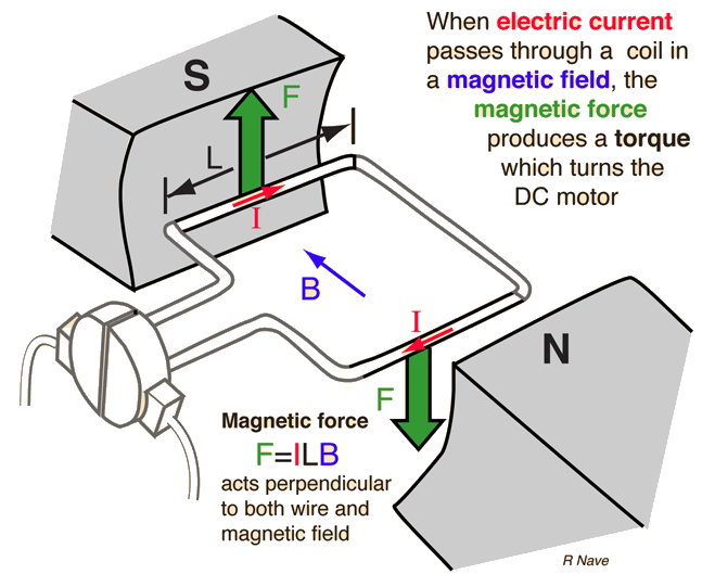
| Index Magnetic field concepts Magnetic force applications | |
| HyperPhysics***** Electricity and Magnetism | Go Back |
Torque in DC Motor
| DC Motor Operating Principles | Torque on a Coil |
Brushed DC motors
Main article: Brushed DC electric motor

Many of the limitations of the classic commutator DC motor are due to the need for brushes to press against the commutator. This creates friction. Sparks are created by the brushes making and breaking circuits through the rotor coils as the brushes cross the insulating gaps between commutator sections. Depending on the commutator design, this may include the brushes shorting together adjacent sections—and hence coil ends—momentarily while crossing the gaps. Furthermore, the inductance of the rotor coils causes the voltage across each to rise when its circuit is opened, increasing the sparking of the brushes. This sparking limits the maximum speed of the machine, as too-rapid sparking will overheat, erode, or even melt the commutator. The current density per unit area of the brushes, in combination with their resistivity, limits the output of the motor. The making and breaking of electric contact also causes electrical noise, and the sparks additionally cause RFI. Brushes eventually wear out and require replacement, and the commutator itself is subject to wear and maintenance (on larger motors) or replacement (on small motors). The commutator assembly on a large motor is a costly element, requiring precision assembly of many parts. On small motors, the commutator is usually permanently integrated into the rotor, so replacing it usually requires replacing the whole rotor.
Large brushes are desired for a larger brush contact area to maximize motor output, but small brushes are desired for low mass to maximize the speed at which the motor can run without the brushes excessively bouncing and sparking (comparable to the problem of "valve float" in internal combustion engines). (Small brushes are also desirable for lower cost.) Stiffer brush springs can also be used to make brushes of a given mass work at a higher speed, but at the cost of greater friction losses (lower efficiency) and accelerated brush and commutator wear. Therefore, DC motor brush design entails a trade-off between output power, speed, and efficiency/wear.

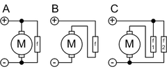
A: shunt
B: series
C: compound
f = field coil
B: series
C: compound
f = field coil
- DC shunt-wound motor
- DC series-wound motor
- DC compound motor (two configurations):
- Cumulative compound
- Differentially compounded
- Permanent magnet DC motor (not shown)
- Separately excited (not shown)
Coreless or ironless DC motors
Nothing in the principle of any of the motors described above requires that the iron (steel) portions of the rotor actually rotate. If the soft magnetic material of the rotor is made in the form of a cylinder, then (except for the effect of hysteresis) torque is exerted only on the windings of the electromagnets. Taking advantage of this fact is the coreless or ironless DC motor, a specialized form of a brush or brushless DC motor. Optimized for rapid acceleration, these motors have a rotor that is constructed without any iron core. The rotor can take the form of a winding-filled cylinder, or a self-supporting structure comprising only the magnet wire and the bonding material. The rotor can fit inside the stator magnets; a magnetically soft stationary cylinder inside the rotor provides a return path for the stator magnetic flux. A second arrangement has the rotor winding basket surrounding the stator magnets. In that design, the rotor fits inside a magnetically soft cylinder that can serve as the housing for the motor, and likewise provides a return path for the flux.Because the rotor is much lighter in weight (mass) than a conventional rotor formed from copper windings on steel laminations, the rotor can accelerate much more rapidly, often achieving a mechanical time constant under 1 ms. This is especially true if the windings use aluminum rather than the heavier copper. But because there is no metal mass in the rotor to act as a heat sink, even small coreless motors must often be cooled by forced air.
Related limited-travel actuators have no core and a bonded coil placed between the poles of high-flux thin permanent magnets. These are the fast head positioners for rigid-disk ("hard disk") drives.
Universal motors

Modern cheap universal motor, from a vacuum cleaner
Operating at normal power line frequencies, universal motors are often found in a range rarely larger than 1000 watt. Universal motors also form the basis of the traditional railway traction motor in electric railways. In this application, the use of AC to power a motor originally designed to run on DC would lead to efficiency losses due to eddy current heating of their magnetic components, particularly the motor field pole-pieces that, for DC, would have used solid (un-laminated) iron. Although the heating effects are reduced by using laminated pole-pieces, as used for the cores of transformers and by the use of laminations of high permeability electrical steel, one solution available at start of the 20th century was for the motors to be operated from very low frequency AC supplies, with 25 and 16.7 Hz operation being common. Because they used universal motors, locomotives using this design were also commonly capable of operating from a third rail powered by DC.
An advantage of the universal motor is that AC supplies may be used on motors which have some characteristics more common in DC motors, specifically high starting torque and very compact design if high running speeds are used. The negative aspect is the maintenance and short life problems caused by the commutator. Such motors are used in devices such as food mixers and power tools which are used only intermittently, and often have high starting-torque demands. Continuous speed control of a universal motor running on AC is easily obtained by use of a thyristor circuit, while multiple taps on the field coil provide (imprecise) stepped speed control. Household blenders that advertise many speeds frequently combine a field coil with several taps and a diode that can be inserted in series with the motor (causing the motor to run on half-wave rectified AC).
Induction motors can't turn a shaft faster than allowed by the power line frequency. By contrast, universal motors generally run at high speeds, making them useful for appliances such as blenders, vacuum cleaners, and hair dryers where high speed and light weight is desirable. They are also commonly used in portable power tools, such as drills, sanders, circular and jig saws, where the motor's characteristics work well. Many vacuum cleaner and weed trimmer motors exceed 10,000 RPM, while Dremel and other similar miniature grinders will often exceed 30,000 RPM.
Universal motors also lend themselves to electronic speed control and, as such, are an ideal choice for domestic washing machines. The motor can be used to agitate the drum (both forwards and in reverse) by switching the field winding with respect to the armature. The motor can also be run up to the high speeds required for the spin cycle.
Motor damage may occur from overspeeding (running at an rotational speed in excess of design limits) if the unit is operated with no significant load. On larger motors, sudden loss of load is to be avoided, and the possibility of such an occurrence is incorporated into the motor's protection and control schemes. In some smaller applications, a fan blade attached to the shaft often acts as an artificial load to limit the motor speed to a safe level, as well as a means to circulate cooling airflow over the armature and field windings.
Energy conversion by an electric motor
Using mathematical models in terms of a magnetic dipole, Ribarič and Šušteršič[24] consider how in the case of the synchronous motor and induction motor an external source is supplying electrical energy to the stator so as to maintain its revolving magnetic field; this energy is then transmitted by the revolving magnetic field to the magnetic dipole of the rotor; there it is converted into mechanical energy, and transmitted mechanically by the rotating shaft to an external user. On the other hand, in the case of a commutator motor, the external source delivers electrical energy directly to the rotor magnetic dipole for conversion into mechanical energy.Power
The power output of a rotary electric motor is:
And for a linear motor:

Efficiency
To calculate a motor's efficiency, the mechanical output power is divided by the electrical input power:,where η is energy conversion efficiency, Pe is electrical input power, and Pm is mechanical output power.
In simplest case Pe = VI, and Pm = Tω, where V is input voltage, I is input current, T is output torque, and ω is output angular velocity. It is possible to derive analytically the point of maximum efficiency. It is typically at less than 1/2 the stall torque.
Goodness factor
Professor Eric Laithwaite proposed a metric to determine the 'goodness' of an electric motor:[25]Where:
- G is the goodness factor (factors above 1 are likely to be efficient)
- Am,Ae are the cross sections of the magnetic and electric circuit
- lm,le are the lengths of the magnetic and electric circuits
- μ is the permeability of the core
- ω is the angular frequency the motor is driven at

No comments:
Post a Comment